
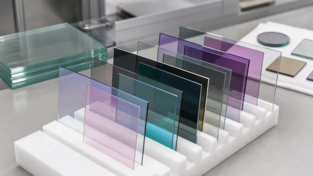
Key Takeaways
- A complete custom glass coating specification defines spectral performance, substrate material, geometry, surface quality, and environmental durability.
- Matching the coating stack to the glass substrate material is critical for adhesion and spectral performance.
- Inspection requirements—such as spectrophotometry and scratch-dig—must be defined during the design phase.
- Using a visual 3D configurator helps clarify custom geometry before detailed RFQ preparation.
Getting the Coating Right Starts with the Specification
When an optical engineer or sourcing team begins a custom glass window project, the coating requirements often determine the component’s final performance. Specifying the right coating type, on the proper substrate, with clear geometric and surface-quality requirements from the outset prevents costly redesigns and production delays. A precise coated glass specification for custom glass windows captures the interplay between substrate, dimensions, finish, and functional layers.
Why Coating Specifications Matter for Precision Glass
Coatings control reflection, transmission, conductivity, and durability. In high-precision applications, even small deviations in thickness, adhesion, or uniformity degrade performance. When a design depends on anti-reflective behavior, conductive traces, or spectral filtering, the tolerance stack begins with the base glass. A poorly defined coating spec leads to rework, extended timelines, and mismatched performance. Suppliers need complete information to select the appropriate deposition method, plan masking, and validate results.
Substrate Materials: Matching Glass to the Coating
The substrate directly affects coating adhesion, optical clarity, and thermal stability. Common precision glass materials include:
- Fused silica and quartz glass – high UV transmission and low thermal expansion, ideal for laser optics and semiconductor windows.
- Borosilicate glasses (e.g., Borofloat 33) – excellent thermal shock resistance, widely used for microscope slides and display cover glass.
- Alkali-free glass – essential for microfluidic chips and biochips to prevent ion leaching into sensitive samples.
- Optical glass (e.g., BK7) – specified for refractive elements where a known index of refraction is critical.
- Sapphire – extreme hardness and high thermal conductivity, chosen for scratch-resistant windows or high-temperature sensors.
Always confirm material compatibility with the coating process and end-use environment. Coefficients of thermal expansion and surface chemistry influence film stress and long-term reliability.
Geometry and Drawing Requirements
Every coated region, edge exclusion, and fiducial must appear on the engineering drawing. Key geometry parameters include:
- Outer dimensions (length, width, diameter) and thickness.
- Hole positions, slot geometries, and edge chamfers.
- Flatness and wedge angle for optical windows.
- Alignment features (notches, flats, or printed markers) for precise coating placement.
For microfluidic glass chips, channel depths and cover glass thickness become part of the coating specification. Specify uncoated borders when required for bonding or electrical isolation. A complete drawing reduces ambiguity and speeds up engineering review.
Tolerances, Surface Quality, and Edge Finish
Coating uniformity depends on substrate flatness and surface roughness. Define:
- Dimensional tolerances (length, width, diameter, thickness).
- Flatness (total thickness variation, bow, warp) – call out values like “λ/4 at 633 nm” for precision optics.
- Surface quality using scratch-dig standards (e.g., MIL-PRF-13830 or ISO 10110) to limit scatter and defects.
- Edge finish (seamed, ground, or polished) to prevent chipping during handling and coating.
State the acceptable cosmetic defect level on the coated surface. A well-defined surface spec prevents disagreements during incoming inspection.
Coating and Functional Layers
Describe the coating type, spectral performance, and any additional functional requirements:
- Optical coatings – anti-reflective (AR), high-reflective, beamsplitter, or dielectric filter. Provide wavelength range, angle of incidence, and reflectance/transmission targets.
- Conductive coatings – ITO or FTO for transparent electrodes. Include sheet resistance and optical transmission specifications.
- Metallization – gold, aluminum, or other metals for electrical contacts or reflectors.
- Edge deletion – areas where the coating must be removed for electrical isolation, often done via laser ablation or masking.
- Etched features – grooves, cavities, or fiducials that may require coating inside or on the bottom.
- Cleanliness requirements – particle and outgassing limits for vacuum or medical applications.
All these details become part of the coated glass specification and affect both cost and lead time.
Key Specification Points to Define Before Requesting a Quote
Compile the following in your RFQ package:
- Substrate material and required thickness.
- Coating type, spectral range, and performance targets.
- Drawing with coated region(s), edge exclusion, and fiducials.
- Surface quality (scratch-dig, flatness, edge finish).
- Any post-coating processing (dicing, bonding, cleaning).
- Environmental or durability requirements (temperature, humidity, UV exposure).
- Target quantity and timeline.
A clear list allows the supplier to quickly assess feasibility and provide an accurate quotation.
Manufacturability Notes for the Supplier
Before production, the supplier must review the process sequence. Coating is often performed after polishing and cleaning. Edge chipping is a known risk when cutting coated glass, so the machining order must be planned. Surface activation before coating ensures adhesion, especially on chemically resistant glasses. For conductive ITO/FTO coatings, edge deletion may require laser ablation that must not damage the underlying glass. Inspection methods (spectrophotometry, profilometry, adhesion testing) must be agreed upon. Finally, packaging must guard against scratches and contamination during shipment.
Visual Specification Support with the 3D Configurator
For custom geometries, the Precision Glass 3D Configurator at https://machiningglass.com/3d-glass-builder/ helps engineers build a visual 3D preview of a glass window or substrate. Select a product module such as optical window, ITO/FTO conductive glass, or custom glass plate, then copy an RFQ summary and attach your coating drawing for engineering review. It clarifies design intent before formal quoting, but should not replace final drawing approval.
Next Step: Send Your Specifications for Review
To confirm manufacturability and get a design-focused quote, send your drawings, material requirements, tolerances, coating specifications, and application details to our engineering team. We will evaluate the substrate, geometry, and coating stack together and propose a production-ready solution.
Defining Coating Requirements for Custom Glass Windows and Substrates
Specifying coatings for custom glass windows and substrates begins with a clear definition of spectral performance, environmental durability, and any functional properties (conductivity, anti-reflection, filtering). This section outlines how to convert application needs into documented coating specifications that a precision glass manufacturer can review.
Selecting the Right Coating Type
The coating you specify depends heavily on the intended optical or electronic function:
- Anti-Reflection (AR) coatings reduce surface reflections across a defined wavelength band, increasing transmission. They are critical for windows in imaging systems, laser optics, and displays.
- ITO/FTO conductive coatings add electrical conductivity while maintaining transparency. Use for touch screens, EMI shielding, or electrode layers in microfluidic devices.
- Optical filter coatings (bandpass, longpass, notch) selectively transmit or block wavelengths. They must be paired with a substrate of appropriate transmission range.
- Beam splitter coatings divide incoming light by wavelength or intensity, often requiring tight control of reflection/transmission ratios.
- Metallization or mirror coatings provide high reflectivity in UV, visible, or IR regions, demanding precise film thickness control.
Each coating type requires the engineer to define center wavelength, bandwidth, angle of incidence, and target performance levels. Submitting these parameters early ensures the coating design is matched to the correct precision glass materials and coatings.
Performance Specifications for Coated Glass Substrates
To avoid ambiguity, include these specifications in your drawing or spec sheet:
- Spectral range – Wavelengths of interest (e.g., 400–700 nm, 8–12 µm).
- Incidence angle – 0° (normal), 45°, or a range for variable-angle applications.
- Transmittance or reflectance targets – Average or minimum values over the band (e.g., Tavg > 99% at 550 nm, R < 0.5%).
- Polarization sensitivity – Specify if the coating must perform for s‑polarized, p‑polarized, or unpolarized light.
- Durability requirements – Adhesion (tape test per ASTM D3359), moderate abrasion, humidity exposure, or thermal cycling. Reference industry standards like MIL‑C‑48497 only if your application requires certified compliance.
- Environmental stability – Operating temperature range, UV exposure resistance, and chemical inertness to cleaning agents.
When high transmission is the priority, selecting ar‑coated glass materials with a coating stack optimized for your substrate index can yield superior performance.
Coating–Glass Material Compatibility
The substrate glass strongly influences coating adhesion and stress. Key considerations include:
- Fused silica and quartz glass offer low thermal expansion and high UV transparency, making them ideal for UV coatings and high‑power laser windows.
- Borosilicate glass (e.g., Borofloat 33) provides good thermal shock resistance and is often used with conductive coatings for microfluidic chips.
- Alkali‑free glass minimizes ionic contamination, which is critical for certain conductive coatings and semiconductor‑adjacent applications.
- Optical glass (e.g., N‑BK7) covers visible to near‑IR wavelengths and is frequently paired with broadband anti‑reflection coatings.
- Sapphire provides extreme hardness and broad transmission; coatings must withstand high‑temperature deposition processes.
Always confirm with the coating supplier that the selected substrate material and geometry (especially thickness and edge features) are compatible with the deposition process.
Quality and Inspection Requirements
Define how the coated glass will be inspected and accepted. Typical checks include:
- Spectrophotometry – Verify transmission/reflection against specification over the full wavelength range.
- Surface quality (scratch‑dig) – Inspect per ISO 10110 or MIL‑PRF‑13830, especially if coating may highlight substrate defects.
- Adhesion testing – Cross‑hatch tape test to confirm coating integrity after cleaning or handling.
- Environmental testing – Humidity, thermal shock, or salt fog as agreed, depending on end‑use.
- Uniformity – Map coating thickness or color variation across the aperture, particularly for large windows.
These inspection criteria should be written into the RFQ so that the coating process and acceptance limits are aligned.
Coating Specification Overview
| Specification Aspect | Key Points to Define |
|---|---|
| Substrate Material | Fused silica, borosilicate (Borofloat 33), alkali‑free glass, optical glass, sapphire—selection impacts transmission range, CTE, and coating adhesion |
| Geometry & Tolerances | Dimensions, thickness, holes/slots, edge bevels; flatness, TTV, parallelism; refer to drawing specifications |
| Surface Finish | Scratch‑dig rating, polish level, edge finish; surface quality must be compatible with coating requirements |
| Coating Definition | Type (AR, ITO, filter, etc.), spectral band, incidence angle, reflectivity/transmittance targets, polarization needs, edge deletion if required |
| Durability & Environment | Adhesion, abrasion, humidity, thermal cycling, chemical resistance; reference applicable standards or test protocols |
| Inspection & Testing | Spectrophotometry range, scratch‑dig inspection, uniformity mapping, environmental test conditions, acceptance criteria |
To confirm coating manufacturability on your custom glass window or substrate, send your drawings, material selection, spectral targets, and durability requirements to our engineering team for review. If you have used the 3D Configurator to preview your part, attach the RFQ summary along with your coating specification document.
Frequently Asked Questions
What parameters must I include when specifying a coated glass window?
You should specify wavelength range, incidence angle, target reflectance or transmittance, durability requirements, and the glass substrate material. Also include dimensions, surface quality, and any masking or edge deletion needs.
How do I choose between AR, ITO, or filter coatings for my glass substrate?
AR coatings maximize transmission over a defined band; ITO/FTO coatings add electrical conductivity; filter coatings selectively transmit or reflect wavelengths. The choice depends on whether the window serves as a protective barrier, a sensing element, or an optical filter.
What are the typical durability requirements for coated glass windows?
Durability specs often include adhesion (tape test), abrasion resistance, humidity exposure, and thermal cycling. Military standards like MIL-C-48497 are sometimes referenced, but exact test conditions should be agreed with the coating supplier.
Can I apply a coating after machining holes or features in the glass?
Yes, typically coating is performed after all machining and cleaning steps to ensure uniform coverage and avoid edge defects. Engineering review will determine the optimal sequence.
How does substrate material affect coating performance?
The coefficient of thermal expansion, chemical composition, and surface properties of materials like fused silica, borosilicate, or soda-lime glass influence coating adhesion and stress. High-purity substrates generally support higher-performance optical coatings.