
Key Takeaways
- Always define glass material type, thickness, and orientation before specifying tolerances.
- Internal corner radii and realistic hole geometries are essential for machinability and to avoid cracking.
- Include all surface quality, edge finish, and coating requirements directly on the engineering drawing.
- Use the 3D Configurator to visualize your design and create an RFQ summary, but rely on an engineering review for final manufacturability.
- Submit a complete drawing and specification package to verify design intent before tooling begins.
Start with the single most important design rule
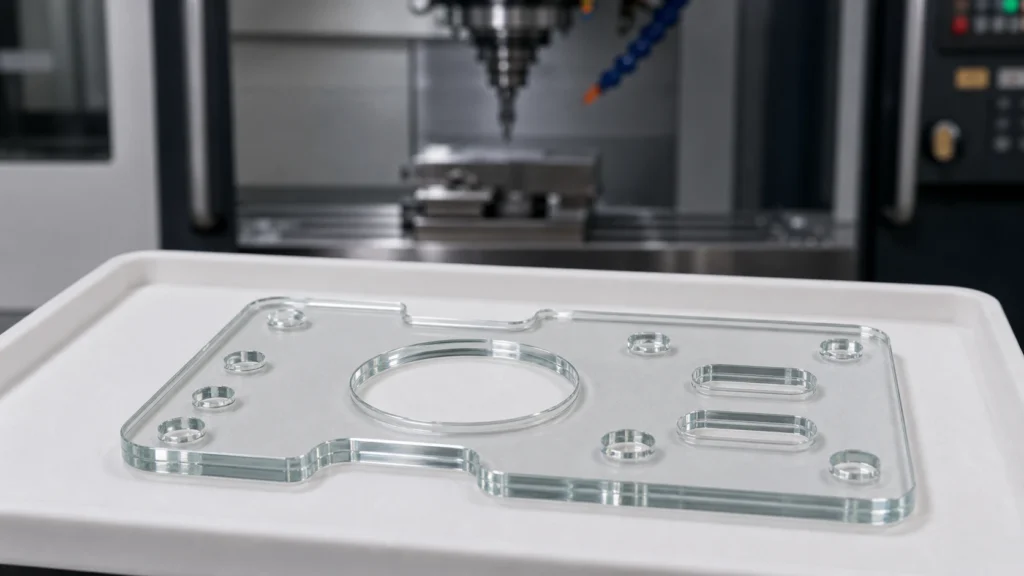
CNC machined glass components demand that you design for the material’s brittleness from the start. Unlike metals, glass fractures rather than deforms, so sharp internal corners, thin walls and sudden cross‑section changes concentrate stress. The path to a successful part begins by respecting these limits in your 3D model and 2D drawing. When you specify the right material, realistic tolerances and machining‑aware geometry, you get repeatable, high‑yield precision glass parts that meet optical, mechanical and chemical requirements.
Why these design choices matter
Precision glass machining is a subtractive process where tooling, coolant and vibration all influence edge strength and surface integrity. Every feature you add—a hole, a slot, a step, a bevel—introduces a potential fracture origin. Getting the design right upfront reduces scrap, shortens lead times and ensures that the finished component performs reliably in laser optics, semiconductor equipment, microfluidics or imaging systems. Suppliers need clear, complete specifications to assess manufacturability and quote accurately.
Material considerations for CNC machined glass
The glass type governs machining behaviour and final properties:
- Fused silica – extremely low thermal expansion, excellent transmission from UV to IR, ideal for laser windows and high‑temperature optics.
- Quartz glass – similar to fused silica; often chosen for high‑purity applications.
- Borosilicate (e.g. Borofloat 33) – good thermal shock resistance, widely used for sight glasses and microfluidic chips.
- Alkali‑free glass – preferred for thin‑film transistor (TFT) substrates and electronic packaging where ionic contamination must be avoided.
- Optical glass (e.g. BK7) – available in many refractive indices; used for filters, beamsplitters and cover glasses.
- Sapphire – extreme hardness and scratch resistance; often machined with diamond tooling for scratch‑resistant windows.
Always state the glass type, trade name or Schott equivalent on the drawing. A material data sheet alone is not enough; the machining shop must understand how the specific glass composition behaves under diamond grinding and drilling.
Geometry and drawing requirements
Define the part thoroughly in your CAD file and 2D drawing:
- Dimensions – overall length, width and thickness as the baseline. Mark critical‑to‑function dimensions with tighter tolerances.
- Thickness – glass wafers are typically supplied in standard thicknesses; specify if you require a custom grind‑to‑thickness operation.
- Holes and slots – minimum diameter should reflect the glass’s strength. Through‑holes are easier than blind holes. Avoid holes too close to the edge (edge distance ≥ 1.5× material thickness is a common starting rule).
- Slots and grooves – radius internal corners; sharp corners will crack. Use generous fillets.
- Orientation features – notches, flats or alignment marks help assembly; specify them with tolerances.
- Special shapes – non‑rectangular outlines (round, D‑cut, stepped) require additional programming; include a fully dimensioned profile.
For microfluidic chips, define channel width, depth and aspect ratio. For optical windows, indicate the clear aperture and any edge bevels.
Tolerance and surface requirements
These parameters directly affect yield:
- Dimensional tolerance – ±0.1 mm is achievable for most features; tighter tolerances increase cost and may require sequential machining steps.
- Flatness / Total Thickness Variation (TTV) / Bow/Warp – critical for wafers and optical plates. Specify the acceptable deviation over the entire surface.
- Parallelism – especially important for beamsplitters and laser optics; measured as wedge angle or thickness difference.
- Surface quality (scratch‑dig) – define per MIL‑PRF‑13830 or ISO 10110. Polish level (e.g., 40‑20, 60‑40) must be noted.
- Edge finish – seamed, ground, polished or as‑cut; edge chips can be stress risers, so many optical components require a ground edge.
Always reference the standard you are using. The supplier needs to know if you require laser‑quality polish on one or both faces.
Coating and functional requirements
Many glass components need additional treatment. Clarify all functional coatings or features early:
- AR coating – specify wavelength range, angle of incidence and reflectance target. The coating may be applied after machining, so the drawing should state whether edges should be masked.
- Optical filter coating – bandpass, longpass, shortpass; provide spectral curve and tolerance.
- ITO/FTO conductive coating – sheet resistance, transmission requirements and any edge deletion width.
- Etched features – etched grooves, cavities or via holes; define depth and profile.
- Metallization/Bonding – edge metallization, solder pads; detail adhesion layer and metal stack.
- Cleanliness – particulate or outgassing limits for vacuum environments.
Key specification points before requesting a quote
- Glass type and grade
- All dimensions with tolerances
- Flatness, TTV, parallelism and surface quality targets
- Coating or functional requirements
- Edge finish and any rounding or bevels
- Quantity and prototype/pre‑production needs
- Application critical‑to‑quality notes
Manufacturability notes for the engineering review
Before production, the supplier will evaluate:
- Machining risk – features prone to edge chipping, especially when holes are close to edges or walls are thin. Adjusting geometry or using sacrificial edges may be proposed.
- Edge chipping control – through the choice of tooling, coolant and feed rates. Seamed or ground edges can mitigate micro‑cracks.
- Coating sequence – coatings are usually applied after machining, but pre‑coated glass can be machined if the coating is protected.
- Cleaning and handling – precision glass is sensitive to contamination; ultrasonic cleaning and cleanroom packaging may be required.
- Inspection – coordinate measuring machines (CMM), interferometers and scratch‑dig inspection are common methods.
- Packaging – custom trays, anti‑static or vacuum‑sealed packaging is often needed to prevent transit damage.
Visualize your design with the Precision Glass 3D Configurator
When your custom geometry includes features like microfluidic channels, optical apertures or ITO patterns, a 3D preview can help communicate intent before formal engineering review. The online tool at https://machiningglass.com/3d-glass-builder/ allows you to select a product module such as glass wafer, microfluidic glass chip, optical filter, ITO/FTO conductive glass, perforated plate, LED/OLED cover glass, AR optical window, beam splitter glass, CCD optical glass plate or glass‑bottom microplate. You can copy an RFQ summary and attach your drawings for a supplier to review. It does not replace a final drawing, but it gives both sides a clearer starting point.
Ready for an engineering review?
Send your drawings, material requirements, tolerances, target quantity and application details. A thorough review will confirm whether your design is ready for precision glass machining and help identify potential issues before tooling begins.
Critical Design Parameters for CNC Machined Glass
To achieve repeatable precision in CNC machined glass components, several design parameters must be specified with care. The following guidelines help avoid manufacturability issues while maintaining the optical or mechanical function of the part.
Internal Corner Radii and Pocket Depth
Rotary CNC tools cannot produce sharp internal corners. A generous internal radius is necessary to prevent stress concentrations that could lead to cracking. While the minimum radius depends on tool diameter and glass type, engineers should always include a radius callout on pockets, slots, and stepped features. As a rule, radii below 0.5 mm require special tooling and may increase machining risk, especially in hard materials like fused silica. Confirm the achievable minimum with your supplier during design review.
Hole and Slot Geometry
Hole diameter should be at least 1.5 times the glass thickness to minimize breakout on exit. For through-holes, consider a chamfer or controlled peck-drilling sequence to reduce edge chipping. Slots with parallel walls benefit from rounded ends rather than square closures. Edge distance—the spacing from a hole edge to the nearest part perimeter—should generally exceed the part thickness. Aspect ratios (depth-to-diameter) for drilled holes beyond 6:1 may require specialized drilling techniques; consult your machinist for feasibility.
Thin Walls and Ribs
Thin, unsupported walls are vulnerable to fracture during machining and handling. A minimum wall thickness depends on overall part size, glass type, and feature orientation. For a typical borosilicate or fused silica component under 100 mm, walls thinner than 1.5 mm should be reviewed carefully. Ribs with a high height-to-width ratio are discouraged unless their function is critical and the design has been vetted for machinability.
Specifying Coatings and Post‑CNC Processing
Coatings such as anti‑reflective (AR) films, ITO conductive layers, or metallic mirrors are applied after CNC machining and thorough cleaning. Any surface to be coated must remain free of pits, scratches, or residue. Specify edge deletion or masked areas directly on the drawing if the coating must avoid certain regions. Keep in mind that optical coatings add a controlled thickness change to the substrate; for interferometric applications, final part dimensions must account for the coating stack. Always include coating specifications—wavelength range, reflectance or transmittance targets, and any environmental durability requirements—in the RFQ package.
Documentation: Drawings, RFQs, and the 3D Configurator
A dimensioned engineering drawing is the foundation of a successful precision glass project. Along with the material callout, the drawing must specify tolerances, surface quality, edge finish, and any unique orientation features or inspection benchmarks. For complex geometries such as microfluidic chips, perforated plates, or optical windows with coatings, the Precision Glass 3D Configurator can serve as a visual communication aid. It lets you select a product module, preview a 3D representation, and copy an RFQ summary to accompany your drawing. The tool is useful for aligning intent before formal engineering review, but it does not replace a detailed, tolerance‑annotated drawing or the back‑and‑forth needed to verify material compatibility and manufacturability.
| Design Aspect | Key Specification Points |
|---|---|
| Material | State glass type (e.g., fused silica, Borofloat 33, optical glass), grade, and any required certifications or orientation of as‑supplied stock. |
| Geometry | Define thickness, outer dimensions, hole/slot sizes, internal radii, chamfers, and positional tolerances. Avoid sharp internal corners and unrealistic aspect ratios. |
| Tolerances & Surface Quality | List flatness, parallelism, TTV, scratch‑dig, and overall dimensional tolerances. Specify polish level and inspection requirements for optical surfaces. |
| Coatings | Include coating type, spectral performance, durability, edge deletion/masking areas, and how coating thickness influences final dimensions. |
| Edge Finish | Call out edge grinding, chamfer angle, and acceptable levels of edge chipping or bevels, especially for parts that will be handled or bonded. |
| Documentation | Provide a dimensioned drawing with all specifications. Use the 3D Configurator to preview geometry and generate an RFQ summary, then confirm every detail with an engineering review. |
For a design that’s ready for production, send your drawings and full specifications for an engineering review. We’ll confirm material compatibility, machinability, and recommend any adjustments before tooling.
Frequently Asked Questions
What tolerances can I expect when CNC machining glass?
Achievable tolerances depend on the glass material, geometry, and feature size. Typical CNC processes can hold dimensional tolerances within ±0.05 mm for many features, but flatness and parallelism limits require separate specification. Exact values should be discussed during an engineering review based on your drawing and application.
How should I define surface flatness and scratch-dig on a glass part drawing?
Use standard optical notation such as λ/4 flatness at 633 nm and scratch-dig per MIL-PRF-13830 or ISO 10110-7. Indicate whether the requirement applies to one surface or both, and note any clear aperture. Provide these values in the drawing’s surface quality callout.
What is the minimum internal corner radius for CNC machined glass features?
Radii below 0.5 mm are challenging and may require micro-milling tools or laser-assisted machining. The achievable minimum depends on part material and depth; always include a radius callout and confirm feasibility with your manufacturer before finalizing the design.
Can coatings be applied after CNC machining, and how do they affect dimensions?
Yes, anti-reflective, ITO, and other thin-film coatings are typically applied after grinding, polishing, and cleaning. Coatings add a controlled, sub‑micron thickness, so optical designs must account for this stack. Specify masking or edge deletion if needed, and ensure surfaces are free of defects before coating.
What drawing details are essential when requesting a quote for a machined glass component?
Include material, all dimensions with tolerances, surface quality (flatness, scratch-dig), edge finish, coating requirements, and any special cleaning or packaging notes. A 3D view from the configurator can help communicate intent, but a fully dimensioned engineering drawing is required for a formal quote.