
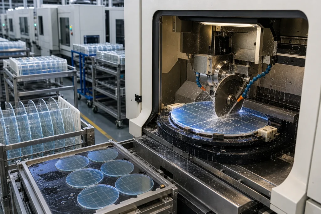
Quick answer: Dicing Borofloat 33 covers Borofloat 33 (CTE 3.25 x 10^-6 /K, 350 nm – 2.0 um); Dicing to +/-0.01 mm index accuracy. Prototypes ship in 5-10 working days.
We dice Borofloat 33 daily, in thicknesses from 0.05 – 3 mm. The controlling numbers: +/-0.01 mm index accuracy working tolerance, 30 um kerf minimum features, and edge chipping under 15 um off the machine. Where the drawing asks for more, downstream lapping and polishing take over.
Specifications at a glance
| Material | Borofloat 33 (SCHOTT float production, wafer grade) |
|---|---|
| Thermal expansion (CTE) | 3.25 x 10^-6 /K |
| Service temperature | 450 C continuous |
| Transmission range | 350 nm – 2.0 um |
| Density | 2.23 g/cm3 |
| Knoop hardness | 480 kg/mm2 |
| Refractive index | 1.471 @ 587 nm |
| Stock thickness | 0.70 – 25.4 mm |
| Maximum blank size | 500 x 500 mm |
| Process | Dicing |
| Working tolerance | +/-0.01 mm index accuracy |
| Minimum feature | 30 um kerf |
| Surface finish | edge chipping under 15 um |
| Thickness window | 0.05 – 3 mm |
| Edge condition | saw edge, optional etch relief |
| RFQ inputs | PDF/DXF/STEP drawing, quantity brackets, surface and edge spec |
What the process holds
Dicing earns its place through singulating wafers into dies with tight index accuracy and low chipping. Its boundary condition – straight-line cuts only; contours route to laser cutting instead – is the first thing our DFM review checks.
Beyond this page, Borofloat 33 routinely runs through polishing, ultrasonic machining, sandblasting, double-side polishing in our shop – most real parts combine two or three of these steps.
Getting the drawing right
Three items decide most of the cost and lead time on this work:
- Material note: float tin side must be tracked when parts see coating or bonding steps.
- Process boundary: straight-line cuts only; contours route to laser cutting instead.
- Over-specification is the quiet budget killer: a 20/10 scratch-dig face costs roughly three times an 80/50 face, so grade each surface individually.
For the complete framework, see the tolerance design guide and the holes and edges design guide.
Where these parts end up
dicing borofloat 33 shows up across mems devices (cap wafers, TGV substrates, motion-sensor lids); led packaging (groove covers, phosphor carriers, package windows); optical sensors (sensor windows, filter caps, lens covers). Background reading on the underlying material science: SCHOTT BOROFLOAT product page.
Dimensions still moving? Configure this part live in the 3D builder below, or open the full custom glass machining 3D builder to start from a blank canvas.
For adjacent specifications, see ultra-thin glass materials, Borofloat 33 selection guide, thickness and flatness guide.
Common questions
What tolerances are achievable on Borofloat 33 parts?
Ground features hold +/-0.01 mm and lapped thickness reaches +/-0.003 mm. Float tin side must be tracked when parts see coating or bonding steps.
What thickness range do you stock for Borofloat 33?
Standard stock spans 0.70 – 25.4 mm, with blanks up to 500 x 500 mm. Other formats are sourced per order.
How does Borofloat 33 behave under heat?
CTE is 3.25 x 10^-6 /K and continuous service reaches 450 C continuous, which is what drives its use where float-glass flatness off the line matters.
What accuracy does dicing hold?
+/-0.01 mm index accuracy with minimum features of 30 um kerf. Straight-line cuts only; contours route to laser cutting instead.
Specifications on this page were last reviewed by our engineering team in July 2026.