
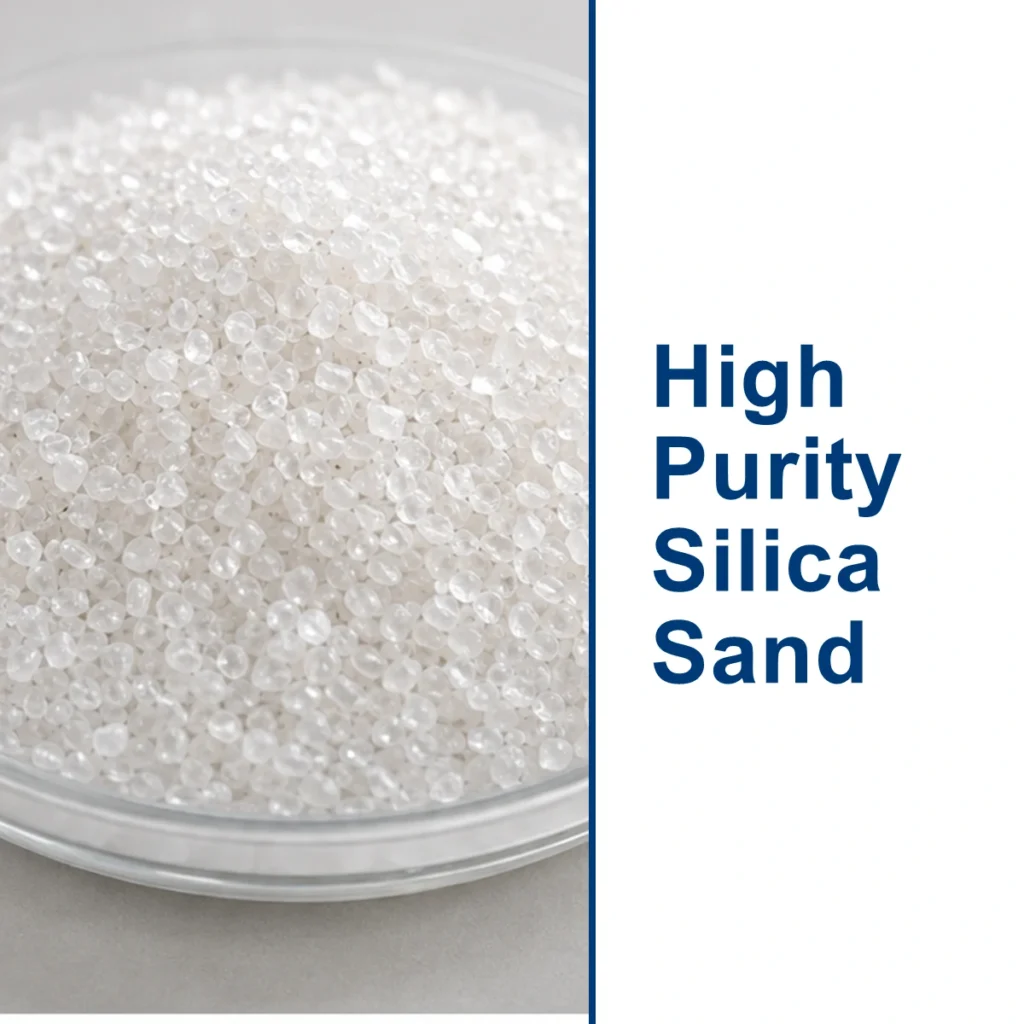
Key Takeaways
- Fused silica wafers provide high UV transmission, low thermal expansion, and excellent chemical resistance for precision optics and semiconductor applications.
- JGS1 grade offers superior UV performance, while JGS2 is a cost-effective alternative for visible to IR applications.
- Surface quality and dimensional tolerances such as scratch-dig, flatness, and TTV are critical and can be customized to application needs.
- Double-side polishing and laser dicing are standard processes to achieve precision wafer specifications.
- For optimal results, pair the wafer material with a compatible AR, ITO, or hydrophobic coating based on operating wavelength and environmental conditions.
Why Glass Material and Coating Choice Defines Wafer Performance
A process engineer loads a 200 mm wafer into a UV lithography tool. Alignment stability across thermal cycles, deep-UV transmission, and resistance to aggressive cleaning chemistries are not optional—they are baseline requirements. The substrate material and its surface finish directly determine whether that wafer yields a robust MEMS device or fails at process qualification. Selecting the right glass is an engineering decision that shapes flatness, surface quality, machinability, and end-use reliability.
Available Glass Materials as Labeled Options
Precision wafer programs typically start by matching the substrate to the optical, thermal, and mechanical demands of the application. Common materials supplied for wafer fabrication include:
- Fused Silica – High‑purity synthetic amorphous SiO₂, available in UV and IR grades.
- Borosilicate – Alkali‑doped silicate glass (e.g., Borofloat‑33 type) with low thermal expansion and good chemical stability.
- Soda‑Lime – Float glass used where cost drives decisions and moderate thermal resistance is acceptable.
- Aluminosilicate – Engineered glass that can be chemically strengthened for high mechanical requirements.
- Sapphire – Single‑crystal Al₂O₃ offering extreme hardness and broad transparency from UV to mid‑IR.
- Optical Glass – Glasses like BK7 or B270 where visible‑range transmission and homogeneity are critical.
Properties and Trade‑offs of Each Glass Type
Fused Silica delivers the lowest coefficient of thermal expansion (~0.55 ppm/°C) of any glass wafer material, enabling it to maintain interferometric flatness across wide temperature swings. UV‑grade material transmits below 200 nm, supporting excimer laser lithography. The material is harder than borosilicate (Mohs ~6.5), demanding diamond‑tooled dicing and slower polishing cycles. Cost per substrate is higher, but justified where thermal stability and UV clarity are non‑negotiable. Fused silica is amorphous and synthetic, offering far greater purity and homogeneity than naturally occurring crystalline quartz.
Borosilicate balances moderate cost with a thermal expansion coefficient near 3.3 ppm/°C. It resists thermal shock well and withstands many acids and solvents, making it a workhorse for microfluidic chips and MEMS substrates that undergo anodic bonding to silicon. Optical transmission drops off below ~300 nm, limiting its use in UV applications. Machining performance is good; it can be laser‑cut or mechanically scribed.
Soda‑Lime is the most economical wafer material, frequently used for disposable diagnostic slides or display‑cover prototypes. It softens at relatively low temperatures and offers poor thermal shock resistance, so it is rarely chosen for processes involving rapid heating. Its strength can be improved by thermal tempering, but that can introduce optical distortion.
Aluminosilicate glasses can be chemically strengthened via ion exchange to achieve a high surface compressive stress layer, resisting impacts and scratches. This makes them suitable for thin, durable cover wafers in consumer‑industrial displays. They typically offer better thermal endurance than soda‑lime but remain below the performance of fused silica or borosilicate in extreme chemical or UV environments.
Sapphire presents a unique trade‑off: exceptional hardness (Mohs 9) and scratch resistance, broad wavelength transparency, and high thermal conductivity. However, it is expensive, available in smaller diameters, and difficult to machine—any via drilling or edge profiling requires diamond abrasives and prolonged cycle times. Sapphire wafers are reserved for high‑value applications like severe‑environment sensor windows or optics that must survive abrasive contact.
Optical glasses like BK7 provide excellent visible‑light transmission and refractive index homogeneity. They are supplied in wafer form for precision optical assemblies, beam‑splitters, and micro‑optics replication. Their lower thermal and chemical durability compared to fused silica or borosilicate limits them to benign environments.
Coating and Surface‑Treatment Options and Their Trade‑offs
The as‑formed wafer surface is rarely the final surface. Coatings modify optical, electrical, or mechanical behavior:
- Anti‑Reflective (AR) Coatings – Multilayer dielectric stacks (e.g., MgF₂ or sputtered oxides) reduce reflectivity and boost transmission. Applied on fused silica, they can raise UV‑band throughput above 99%. Adhesion depends on substrate cleaning; a well‑prepared surface is essential to avoid delamination under thermal cycling.
- Mirror Coatings – Protected aluminum or gold coatings create reflective wafers for scanners and interferometers. Gold works from IR to near‑IR but may require a barrier layer for direct bonding.
- ITO (Indium Tin Oxide) Coatings – A transparent conductor used on display or sensor wafers. It adds a conductive path but slightly reduces optical transmission and can degrade under humid conditions unless encapsulated.
- Hydrophobic/Oleophobic Coatings – Fluorinated monolayers reduce surface energy and make the wafer easier to clean or less prone to sample carryover in microfluidics. They are thin and may wear with repeated handling.
- Thermal Tempering – For soda‑lime wafers, a controlled heat‑and‑quench cycle creates compressive stress for improved mechanical strength, though it may warp thin wafers. Not applicable to fused silica or borosilicate.
- Chemical Strengthening – Ion‑exchange in aluminosilicate wafers drives potassium ions into the surface, producing high compression strength. This process follows pre‑machining to final dimension and does not alter optical transmission.
Matching Material and Coating to Application
The selection matrix starts with the end process:
UV lithography masks demand fused silica with UV‑AR coatings; any substrate with lower transmission or higher CTE will degrade alignment. MEMS wafers that require anodic bonding to silicon are almost always borosilicate to match expansion during bonding. Microfluidic chips that require low autofluorescence choose fused silica or borosilicate, depending on chemical exposure, with hydrophobic coatings to manage fluid flow. Display‑cover wafers for outdoor equipment often use chemically strengthened aluminosilicate with an AR layer and an oleophobic top coat.
Compliance considerations are straightforward for most precision glass wafers. Standard fused silica, borosilicate, soda‑lime, aluminosilicate, and sapphire materials are RoHS and REACH compliant. Some specialty optical glasses may contain lead or arsenic, so confirming the exact glass type against current regulations is advised when they are specified. A manufacturer’s materials declaration can be requested to verify compliance before a wafer program begins.
Machining compatibility should not be overlooked. Fused silica and sapphire require diamond‑tooled grinding and laser dicing techniques that add cost; borosilicate and aluminosilicate are more forgiving with standard abrasives and can be laser‑cut at higher speed. Thin wafers are susceptible to coating‑stress warpage, so an AR coating with matched stress layers or a thin ITO film may be specified to maintain flatness after deposition.
For a production‑optimized material and coating stack, consult our engineering team with your target wavelength range, process temperatures, cleaning chemistry, and bonding requirements. Request a material recommendation and we will propose a substrate–coating combination matched to your precision glass processing workflow.
Precision Manufacturing Specifications for Fused Silica Wafers
Achieving consistent wafer-to-wafer performance in precision glass processing depends on tightly controlled dimensional tolerances and surface quality. When sourcing fused silica wafers, buyers must evaluate parameters such as total thickness variation (TTV), bow, warp, surface roughness, and edge finish to ensure seamless integration into their fabrication workflows.
Dimensional Tolerances and Surface Finish
Standard fused silica wafers are offered in diameters up to 12 inches; see our Fused Silica Glass Wafers (2–12″, JGS1/JGS2) product page for available sizes. Thickness typically ranges from 0.2 mm to several millimetres, with custom thinning possible for microfluidic or MEMS applications. Key specifications include:
- Total Thickness Variation (TTV): Tightly controlled to within a few microns using double-side polishing, critical for bonding and lithography steps.
- Bow and Warp: Minimized through stress-relieved annealing and balanced polishing; values are specified per SEMI standards for wafer shape.
- Surface Roughness (Ra): Achievable below 0.5 nm for super-polished wafers, essential for optical coatings and direct bonding.
- Edge Quality: Edge grinding and polishing remove micro-cracks; laser dicing yields clean, chip-free edges for bio-compatible devices.
Surface Quality and Inspection Standards
Scratch-dig specifications per MIL-PRF-13830B or ISO 10110 are commonly applied. A 20-10 scratch-dig is routine for lapped and polished surfaces, while 10-5 is attainable for critical optics. Visual inspection under high-intensity light ensures freedom from digs, scratches, and inclusions. Fused silica’s hardness (Mohs 5-6) demands diamond-tooled grinding and cerium-oxide-based polishing, with double-side lapping used to achieve parallelism better than 10 arcseconds.
Key Facts About Fused Silica Wafer Manufacturing
- Fused silica wafers are produced in JGS1 (UV-grade, high transmission below 250 nm) and JGS2 (optical-grade, cost-effective for visible to IR) purity levels.
- Typical surface roughness after polishing can reach <0.5 nm Ra, enabling low-scatter optical surfaces.
- Common wafer diameters range from 2 to 12 inches; thinner wafers down to 100 µm are available for flexible electronics and microfluidics.
- Double-side polishing ensures superior parallelism and flatness, often <λ/4 per inch at 633 nm.
- Laser dicing produces clean edges without subsurface damage, critical for MEMS and microfluidic channels.
- For a detailed comparison, see Choosing Between JGS1 and JGS2 Fused Silica.
Custom Machining and Value-Added Services
Beyond standard wafers, precision glass manufacturers offer a range of custom processes to meet exact design requirements:
- Feature Machining: Through-holes, slots, and cavities via ultrasonic drilling or laser ablation, with positional accuracy within ±25 µm.
- Edge Profiling: Rounded, chamfered, or pencil-grind edges to eliminate stress risers and withstand thermal cycling.
- Orientation Features: Notches and flats per SEMI standard for automated wafer handling; laser scribed alphanumeric codes for traceability.
- Cleaning and Packaging: Class 100/ISO 5 cleanroom processing with final inspection; wafers packed in single-slot cassettes or gel-pak trays to prevent surface damage.
Matching Wafer Specifications to Process Requirements
Selection of the right wafer grade and specification should align with the intended process conditions. UV lithography demands JGS1 for its transparency at deep-UV wavelengths, while anodic bonding processes require low alkali content, making fused silica preferable to soda-lime glass. High-temperature SOI or wafer-level packaging steps benefit from the near-zero thermal expansion of fused silica, reducing warpage during thermal cycling. Anticipate downstream processing: a wafer specified with low TTV and minimal bow will simplify photoresist coating uniformity and contact lithography resolution.
| Aspect | Details |
|---|---|
| Material Grades | JGS1 (UV-grade) and JGS2 (optical-grade) fused silica; also borosilicate, aluminosilicate, sapphire |
| Key Properties | High UV transmission (JGS1), low CTE (0.55×10⁻⁶/°C), excellent chemical resistance, high purity, hardness (Mohs 5-6) |
| Typical Applications | Lithography photomasks, MEMS substrates, microfluidics, optical windows, semiconductor packaging |
| Common Coatings | AR (broadband or V-coat), ITO (transparent electrode), hydrophobic (contact angle >110°), mirror (protected Al, Au) |
| Dimensional Specs | Diameter: 2–12″; thickness: 0.1–10+ mm; TTV: <3 µm; surface roughness: <0.5 nm Ra; scratch-dig: 10-5 to 20-10 |
| Quality Standards | MIL-PRF-13830B, ISO 10110, SEMI standards; RoHS/REACH compliance; cleanroom packaging |
| Machining Processes | Double-side polishing, laser dicing, CNC edge grinding, ultrasonic drilling, laser marking |
For your next precision glass project, submit your wafer specifications to receive a detailed quotation including material options, coating recommendations, and lead time estimates. Our engineering team will help refine the specification to balance performance and cost.
Frequently Asked Questions
What is the difference between JGS1 and JGS2 fused silica wafers?
JGS1 is a high-purity UV-grade fused silica with excellent transmission down to 185 nm, making it ideal for deep-UV lithography and spectroscopy. JGS2 is an optical-grade material with slightly higher impurity levels, providing good transmission in the visible to near-IR range at a lower cost. Both offer low thermal expansion and high chemical durability.
What surface roughness can be achieved on fused silica wafers?
Through advanced polishing techniques, fused silica wafers can achieve surface roughness (Ra) below 0.5 nm. This smoothness is essential for reducing scattering in optical applications and enabling direct wafer bonding in MEMS fabrication. The final roughness depends on the polishing process and the specific requirements of the application.
Are fused silica wafers suitable for high-temperature applications?
Yes, fused silica has an extremely low coefficient of thermal expansion (approximately 0.55×10⁻⁶/°C) and can withstand continuous use at temperatures up to 1000°C. This makes it suitable for high-temperature processes such as wafer bonding, thin-film deposition, and thermal treatment in semiconductor manufacturing.
What coatings are commonly applied to fused silica wafers?
Common coatings include anti-reflective (AR) coatings to maximize transmission, indium tin oxide (ITO) for transparent conductive layers, hydrophobic coatings for microfluidic applications, and reflective coatings (aluminum, gold, or dielectric mirrors) for optical components. The choice of coating depends on the operating wavelength, environmental conditions, and functional requirements.
What standard wafer sizes are available in fused silica?
Fused silica wafers are commonly available in diameters from 2 inches (50.8 mm) to 12 inches (300 mm). Thicknesses typically range from 0.2 mm to several millimeters, with custom thinning possible for applications requiring ultra-thin substrates. Standard wafer sizes follow SEMI specifications to ensure compatibility with processing equipment.