
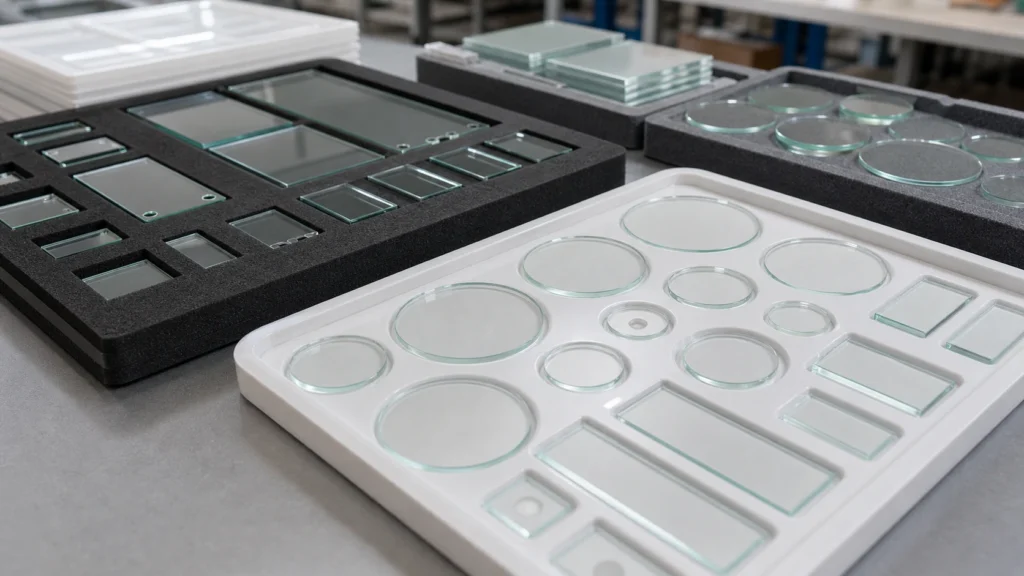
Key Takeaways
- Specify only the tolerances that directly affect part function; over-tolerancing increases cost and lead time without added value.
- Use clear GD&T callouts on drawings and specify flatness, parallelism, and surface quality per industry standards like MIL-PRF-13830 or ISO 10110.
- Material choice constrains achievable tolerances; fused silica permits tighter flatness than many glasses due to lower thermal expansion.
- An early engineering review with the manufacturer confirms that tolerance specs are manufacturable and yields remain high.
- A 3D configurator can preview complex geometries and generate an RFQ summary, but final approval always depends on a fully dimensioned drawing.
The most effective way to specify tolerances for a precision glass part is to begin with its functional role in the final assembly and work backward to the glass material, geometry, and surface finish. Over‑specifying drives up cost unnecessarily; under‑specifying leads to field failures. The right approach links every tolerance value to a measurable performance requirement, ensuring that the glass tolerance specification is lean yet robust.

Why This Specification Matters for Custom Precision Glass Components
Glass is a brittle, elastic material that responds to machining very differently from metals or plastics. Cutting, grinding, and drilling induce micro‑cracks that can propagate if stress is not managed. Precision glass tolerances must balance the functional need with the inherent limits of the material. A tolerance stack-up that works in aluminum often causes edge chipping, breakage during coating, or optical distortion in glass. A clear, complete specification reduces iteration and ensures the supplier can select the right processes—from CNC machining to thermal tempering—before production begins.
Material Considerations for Tolerance Specification
The chosen glass material directly affects achievable tolerances. Fused silica and quartz glass offer exceptional thermal stability and can hold very tight flatness, but they are harder to machine, increasing tool wear. Borosilicate (e.g., Borofloat 33) balances cost and machinability, making it suitable for mid‑range precision. Alkali‑free glass is preferred for microfluidic and semiconductor applications where low ionic content matters. Optical glass and sapphire push dimensional and surface quality to the extreme, but the process chain becomes more complex. For each material, the supplier must review whether required tolerances are feasible without excessive yield loss, especially when combined with coatings or thin profiles.
Geometry and Drawing Requirements
Drawings must unambiguously communicate the part’s critical dimensions, datums, and orientation. For custom machined glass plates, specify length, width, and thickness with tolerance grades. Holes, slots, and grooves should include diameter, position, and edge distance—too close to the edge risks fracture. Orientation features like notches or flats are common for optical windows or CCD glass plates; define them relative to a primary datum. Complex contours or pocket depths require section views. When modeling, consider whether the Precision Glass 3D Configurator can speed early concept verification by generating a visual preview of standard module shapes before finalizing the drawing.
Tolerance and Surface Requirements
Key dimensional controls include linear tolerances (typically in the range of ±0.1 mm for machined glass, tighter for optical), flatness (measured in wavelengths or microns), total thickness variation (TTV), bow/warp, and parallelism. Surface quality is often defined by scratch‑dig specifications (e.g., 60‑40 or 40‑20) or roughness (Ra) for non‑optical surfaces. Polished edges versus ground or seamed edges must be chosen based on handling safety and sealing requirements. No single standard covers all applications; the spec should derive from the part’s optical, mechanical, or bonding function.
Coating or Functional Requirements
Many assemblies require post‑machining coatings: AR coatings on optical windows, ITO/FTO conductive coatings for display or sensor glass, or metallization for bonding. Define the coated surface, coating area, any edge deletion (masked margin), and desired spectral performance. If the part includes an etched groove or cavity, clarify whether coating applies inside that feature. Cleanliness after coating—particle limits, outgassing—is especially important for microfluidic chips or beam splitter glass. The specification must note whether the glass requires baking, UV‑ozone cleaning, or other conditioning before the coating step.
Key Specification Points
- Material type and grade (include trade name if proprietary).
- All overall dimensions with tolerances (length, width, thickness).
- Flatness, TTV, bow, and parallelism values (or reference standard).
- Surface quality: scratch‑dig, roughness (Ra), polish level on each face.
- Edge finish: polished, ground, seamed, or as‑cut.
- Features: holes, slots, grooves with positional tolerance and edge distance.
- Coatings: type, wavelength range, reflectance/transmittance specs, edge deletion width.
- Inspection and packaging requirements (cleanroom packaging, particle specifications).
- Any special handling or certification needs.
Manufacturability Notes
Before production, the glass supplier reviews the full specification to assess machining risks. Edge chipping is a primary concern for thin walls or small corner radii; internal radii should be as large as practical. Coating sequence matters—applying coating before final grinding can damage the film, while coating after may require masking or re‑cleaning. Cleaning protocols must be matched to the material and coating type. Inspection often requires non‑contact optical metrology for fragile parts, and packaging must protect against scratches and vibration during export shipping. When a feature pushes the limits of the chosen material, the supplier may propose an alternative geometry or a slightly relaxed tolerance to maintain yield without compromising function.
Optional 3D Configuration
For custom geometries that benefit from a fast visual reference, the Precision Glass 3D Configurator can help. You can select a product module—glass wafer, microfluidic glass chip, optical filter, ITO/FTO conductive glass, perforated plate, LED/OLED cover glass, AR optical window, beam splitter glass, CCD optical glass plate, glass‑bottom microplate, or custom glass—and generate a 3D preview. The tool allows you to copy an RFQ summary and attach your finished drawing for a comprehensive engineering review. It is a specification support tool, not a replacement for a fully dimensioned drawing.
Request an Engineering Review
Send your drawings, material requirements, tolerance stack‑up, estimated quantities, and application details to our team. An early review identifies critical constraints and ensures that your precision glass tolerance specification aligns with economical, high‑yield manufacturing.
How to Specify Tolerances for Your Precision Glass Component
To specify tolerances for precision glass parts, define the allowable deviation for each critical parameter—dimensions, flatness, parallelism, and surface quality—then document them clearly in your drawing and RFQ. Every tolerance should reflect a functional requirement, not an arbitrary tight number, because tighter tolerances directly increase cost and lead time.
Assign Sensitivity to Each Feature
Not every dimension drives performance. Identify features that influence optical alignment, fluidic flow, mechanical fit, or coating uniformity. For example, the diameter of a microfluidic chip channel may need a tighter tolerance than the outer perimeter. Label these as critical on the drawing and provide tolerance bands accordingly.
Communicate Tolerances on Engineering Drawings
Use standard geometric dimensioning and tolerancing (GD&T) symbols where applicable. Note flatness in waves or microns, scratch-dig per MIL-PRF-13830 or ISO 10110, and parallelism in arc minutes or microns. Specify edge finish, bevels, and any orientation features. A clean drawing that flags all tolerance callouts reduces ambiguity and prevents rework.
Standard Tolerance Guidelines for Glass Machining
While no universal standard exists for all glass processes, typical machining capabilities for CNC-ground and polished parts fall within certain ranges. Dimensional tolerances of ±0.1 mm are common for larger features, while ±0.02 mm or tighter can be achieved for holes and slots when using appropriate tooling and process control. Flatness may range from 1λ to λ/10 depending on the material and polishing sequence. Always confirm achievable tolerances with your supplier during the engineering review, as material properties like brittleness and thermal expansion influence results. For aspects such as precision glass grinding and precision glass material selection, an early feasibility check ensures that your specified tolerances align with process capabilities.
Preparing Your RFQ for Tolerance-Critical Glass Parts
Supply a fully dimensioned drawing that includes all tolerance blocks and surface quality specs. Note the material grade, quantity, and any special cleaning, packaging, or coating requirements. If your part involves custom geometries—such as asymmetric cuts, non-standard chamfers, or blind holes—the Precision Glass 3D Configurator can help you visualize the component and copy an RFQ summary before submitting drawings for engineering review. This tool generates a 3D preview from your selected product module (glass wafer, microfluidic chip, optical window, etc.) and streamlines the quoting process without replacing final drawing verification.
| Parameter | What to Define | Relevant Guidance |
|---|---|---|
| Material | Fused silica, borosilicate, optical glass, etc. | Supplier datasheet; thermal and mechanical limits |
| Dimensions | Length, width, thickness, hole locations; use GD&T | ISO 2768, ASME Y14.5; critical features flagged |
| Flatness | Waves or microns; specify over clear aperture | MIL-PRF-13830, ISO 10110 |
| Surface Quality | Scratch-dig, roughness | 60-40 typical for imaging; tighter for laser optics |
| Edge Finish | Ground, polished, seamed; bevel angles | Customer-defined; affects chamfer and chipping risk |
| Coatings | AR, ITO, filters; include wavelength and performance | Spec sheets; confirm coating temperature limits |
| Cleanliness | Particle count, packaging | ISO 14644 class or visual inspection criteria |
Request a Tolerance Review
Send your drawings, material requirements, tolerance stack-up, estimated quantities, and application details to our team. An early review identifies critical constraints and ensures that your tolerance specification aligns with economical, high-yield manufacturing.
Frequently Asked Questions
What are typical dimensional tolerances for precision glass parts?
Typical linear tolerances for CNC-machined precision glass components are ±0.1 mm for larger features, with tighter tolerances down to ±0.02 mm or less for critical holes and slots. However, the exact capability depends on the glass type, feature geometry, and process sequence, which should be confirmed during an engineering review.
How do I specify flatness on a precision glass drawing?
Flatness is usually specified in waves or microns over a clear aperture, referencing standards such as MIL-PRF-13830 or ISO 10110. The value reflects the allowable deviation from an ideal plane; common callouts range from λ to λ/10 for high-precision optics, but achievable flatness varies with material and polishing method.
Can tight tolerances be held on holes and slots in glass?
Yes, precision glass drilling and slotting can achieve positional tolerances of ±0.02 mm or better when proper tooling and process control are used. However, edge chipping and micro-cracking risks increase with very tight specs, so feature size, edge distance, and material type must be evaluated during design.
What scratch-dig specification should I choose for my glass part?
Scratch-dig numbers follow the MIL-PRF-13830 standard, with common specs like 60-40 for imaging windows and 20-10 for laser-quality surfaces. Tighter specs raise cost and yield loss, so select the value based on actual optical path sensitivity; non-imaging covers or protective windows can often use 80-50 or industrial polish.
Does a coating process affect glass tolerance specifications?
Yes, coatings such as AR or ITO are applied at elevated temperatures, which can induce subtle substrate warping or change stress profiles. It's important to specify final coated flatness or transmitted wavefront error if critical, and to confirm with the manufacturer that the coating process is compatible with the base glass material and tolerance targets.