
Key Takeaways
- Edge finish and chipping allowance must be defined on the drawing to ensure part strength and optical performance.
- Drilling sequence relative to coating application directly impacts hole‑wall quality and edge defects.
- Inspection methods for glass edges and holes include optical comparators, CMM, and non‑contact profilometry.
- Use the 3D Configurator to visualize geometry and prepare RFQs, but final design review by engineering is essential.
When engineers design custom glass parts with holes, slots, or critical edge features, the first question is often: “What are the minimum dimensions and tolerances I can specify to ensure the part is manufacturable?” The answer depends on glass material, part geometry, and post-processing requirements, but starting with a clear specification set can prevent costly redesigns.
Why Hole, Slot, and Edge Specifications Matter for Custom Precision Glass
Features such as through-holes for mounting, slots for fluidic channels, and polished edges for optical beam paths directly influence a component’s structural integrity, optical performance, and cleanroom compatibility. Incomplete or over-constrained specifications frequently lead to edge chipping, breakage during handling, or out-of-spec light scattering. Defining these features early in the design phase helps the manufacturer assess machining risk and propose the optimal fabrication sequence.
Material Considerations for Hole and Edge Machining
The glass type dictates how aggressively it can be machined and what edge quality is achievable. Fused silica and synthetic quartz glass offer high UV/IR transmission and thermal stability but are more brittle and require conservative hole-to-edge distances. Borosilicate glass, including Borofloat 33, provides excellent chemical resistance and flatness, making it suitable for microfluidic chips and cover glasses. Optical glasses (e.g., N‑BK7) are used for lenses and filters, while sapphire demands diamond tooling due to its hardness. Alkali‑free glass is preferred for semiconductor and electronic applications where ion migration must be avoided. Suppliers need to know the material grade to assess drilling, slotting, and edge‑finishing capabilities.
Geometry and Drawing Requirements
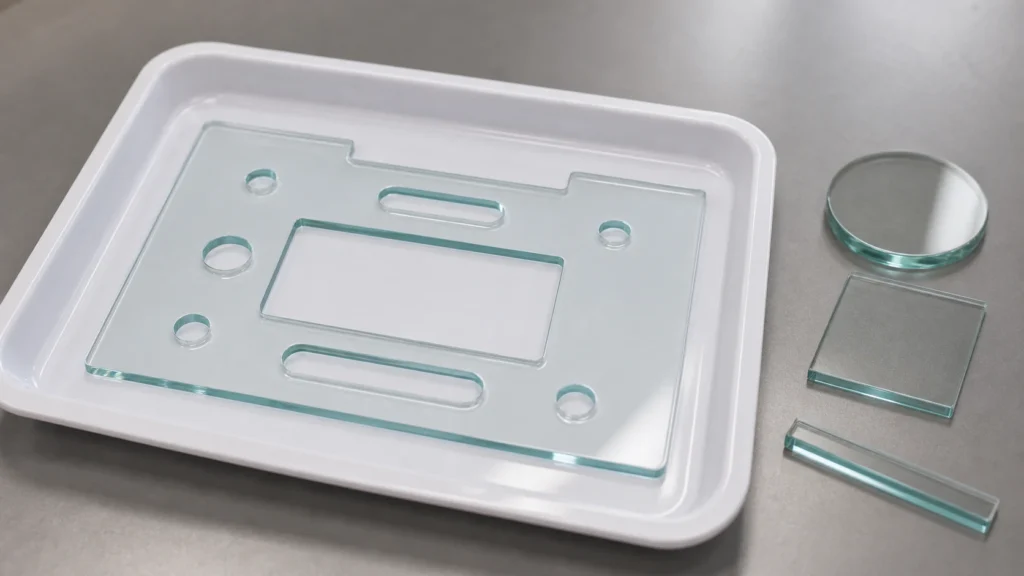
Engineers should clearly indicate on the drawing: part dimensions, thickness, hole diameter and position, slot width and length, minimum distance from hole rim to glass edge, and spacing between adjacent holes. For slots, define the end radius and wall angles. Include any chamfers, rounded corners, or orientation flats. Geometric dimensioning and tolerancing (GD&T) symbols for true position or profile help communicate intent. For complex geometries, engineers can use the Precision Glass 3D Configurator to create a visual 3D preview, select a product module such as perforated plate or microfluidic chip, copy an RFQ summary, and attach drawings for engineering review—this accelerates the feasibility check before formal quoting.
Tolerance and Surface Requirements for Holes, Slots, and Edges
Dimensional tolerances for hole location and diameter in precision glass typically range from ±0.05 mm to ±0.2 mm, depending on the feature size and material; actual capability must be confirmed during engineering review. Flatness, total thickness variation (TTV), and bow/warp should be specified for parts requiring optical contact or bonding. Parallelism between faces is critical for beam-splitter and optical-window applications. Surface quality is expressed as scratch‑dig per ISO 10110 or MIL‑PRF‑13830—e.g., 60‑40 for general-purpose windows, 20‑10 or better for laser optics. Edge finish options include ground, polished, or chamfered; the allowed chipping width (typically ≤0.2 mm unless otherwise specified) should be stated on the drawing to avoid cosmetic rejects. The engineering team will evaluate whether the required tolerances can be held after any coating or thermal processing.
Specifying Edge Finish and Chipping Allowance
Edge finish strongly influences part strength, optical clarity, and assembly fit. For precision glass parts with holes, slots, or profiled perimeters, the drawing should explicitly state the finish type—ground, polished, or chamfered—and the permissible chipping width. A ground edge (typically 80–120 grit) removes subsurface damage, while a polished edge (often with cerium oxide) achieves transparency and reduces light scattering. Chamfered edges, defined by face width and angle, prevent chipping during handling. Allowed edge chipping width is commonly ≤0.2 mm unless the application requires tighter control; this value must be confirmed with the engineering team, as it depends on material, feature geometry, and subsequent coating processes.
Hole and Slot Design for Coated or Multilayer Glass
When through‑holes or slots intersect AR, ITO/FTO, or metallization coatings, the feature sequence matters. Drilling after coating risks delamination and coating edge defects; drilling before coating requires masking or post‑processing to ensure the coating does not bridge or contaminate the hole wall. Specify whether the hole wall should be coated, the acceptable coating edge‑out distance, and any need for precision glass hole drilling parameters that maintain hole‑roundness after thermal cycles. For bonded assemblies, hole‑edge distance and slot‑width tolerances should account for adhesive gap uniformity.
Inspection and Measurement of Edge and Hole Quality
Manufacturers use optical comparators, CMM, and non‑contact profilometry to verify hole position, diameter, edge chipping, and surface roughness. For high‑volume production, custom go/no‑go gauges may be employed. Inspection criteria should be referenced to ISO 10110 or customer‑specific standards. Request sample coupons if first‑article inspection is required, especially when edge chipping limits affect optical path boundaries or hermetic sealing.
| Specification Aspect | Typical Requirement | Notes |
|---|---|---|
| Hole location tolerance | ±0.05–0.2 mm (material‑dependent) | Confirm during engineering review |
| Edge‑to‑hole distance | ≥2× thickness or 6 mm (whichever greater) | Minimizes fracture risk |
| Edge chipping width | ≤0.2 mm (unless tighter specified) | Check after coating if applicable |
| Surface quality (scratch‑dig) | 60‑40 general; 20‑10 laser optics | Specify per ISO 10110 or MIL‑PRF |
| Slot corner radius | ≥0.5 mm (glass thickness ≤3 mm) | Avoid sharp internal corners |
RFQ Checklist and Next Steps
Before submitting drawings for custom glass parts with holes, slots, or profiled edges, engineers should include material grade, tolerances, coating sequences, and edge‑finish specifications. For complex geometries, the Precision Glass 3D Configurator offers a visual preview, module selection (such as perforated plate, optical window, or microfluidic chip), and an RFQ summary to attach to your inquiry. Final manufacturability and tolerance capability will be evaluated by the engineering team. Send your drawings, quantities, and application details for a technical review and quotation.
Frequently Asked Questions
What three specifications are critical when designing holes in glass?
Engineers must define hole diameter tolerance, edge‑to‑hole distance (minimum 2× thickness or 6 mm), and surface quality around the hole. Hole location tolerance and chipping allowance should also be specified on the drawing to avoid misalignment and weakness.
What are the industry standard tolerances for glass edges?
Edge quality is typically specified by surface roughness (Ra) and chipping width. A common chipping allowance is ≤0.2 mm, but this varies with glass type and subsequent processing. Edge profile—ground, polished, or chamfered—should be detailed in the drawing's notes.
How close can a hole be to the edge of a glass part?
The minimum distance from the hole rim to the nearest edge is generally twice the glass thickness or 6 mm, whichever is greater. This prevents fracture during machining and handling. For tempered glass, larger distances may be required; consult the supplier.
Can slots be machined into glass with sharp internal corners?
Sharp internal corners are stress concentrators and should be avoided. A minimum corner radius of 0.5 mm is typical for glass thickness up to 3 mm; thicker glass may require larger radii. Confirm feasibility with the manufacturer during design review.
Does applying an AR coating affect hole edge quality?
Yes, coating processes can alter edge chipping if applied after drilling, or leave coating material inside holes. Specify whether holes should be coated and the acceptable edge‑out distance. The manufacturing sequence must be planned to maintain hole‑wall quality.