
Key Takeaways
- ITO coating combines high optical transparency with low electrical resistivity via magnetron sputtering.
- Substrate material selection—borosilicate, fused silica, or soda-lime—directly impacts thermal and optical performance.
- In-line checks for sheet resistance, transmittance, and flatness ensure batch-to-batch consistency for OEM orders.
- Post-coating annealing stabilizes ITO films, improving adhesion and conductivity.
How ITO Coating Creates Conductive Glass Substrates
The ITO coating process deposits a thin layer of indium tin oxide onto glass to make it electrically conductive while maintaining high optical transparency. This is achieved through magnetron sputtering in a vacuum chamber, followed by precision post-processing to meet exact optoelectronic requirements.
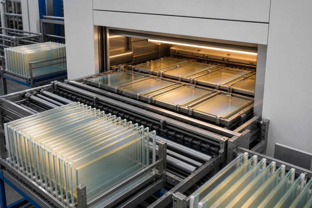
On a production floor, a pristine sheet of borofloat glass is loaded into a cassette and transferred into a Class 1000 cleanroom. Inside, the glass moves through a series of stations—cutting, grinding, polishing, and finally into a sputtering system where a plasma of indium tin oxide is deposited with nanometer precision.
Key Facts About ITO Coating
- Conductive coating: Indium tin oxide (ITO) provides both conductivity and >90% optical transmission.
- Primary method: Magnetron sputtering achieves uniform film thickness and consistent sheet resistance.
- Common substrates: Borosilicate glass, fused silica, soda-lime, and sapphire, selected based on thermal and optical needs.
- Typical applications: Touch screens, flat-panel displays, photovoltaic cells, and EMI shielding.
- Quality critical: Sheet resistance, transmittance, and surface flatness are monitored inline.
Base Glass Materials for ITO Coating
The substrate choice directly influences coating adhesion, thermal stability, and optical performance. Fused silica offers excellent UV transmission and near-zero thermal expansion, making it ideal for precision optics. Borosilicate glass (e.g., Borofloat 33) provides high thermal shock resistance and low alkali content, essential for ITO-coated glass substrate for optoelectronics. Soda-lime glass is a cost-effective option for large-area applications like touch panels, though it has higher thermal expansion. Sapphire, with extreme hardness and IR transparency, suits demanding environments. Optical glass formulations cater to specific refractive index requirements. All substrates undergo rigorous cleaning and inspection before coating to remove surface contaminants and micro-defects.
Manufacturing Stages for ITO-Coated Glass
Glass Cutting and Scribing
Precise dimensions are achieved using CNC scribing machines or diamond-tipped cutting wheels. Tight tolerances are maintained to ensure compatibility with downstream handling and coating fixtures.
Grinding and Lapping
Abrasive slurries on double-side lapping machines remove surface irregularities and achieve uniform thickness. This step corrects for warp and ensures consistent mechanical support during sputtering.
Polishing
Double-side polishing delivers optical flatness and sub-nanometer roughness (Ra <1 nm) critical for uniform ITO film growth. Edge exclusion zones are carefully controlled to prevent roll-off.
Edge Grinding and Beveling
Edges are ground and beveled to eliminate sharp corners and micro-cracks that could propagate or cause particle generation during handling.
Drilling and CNC Machining
Holes, notches, and complex profiles are created with high-speed CNC drills and routers. This is typically performed before coating to avoid damaging the ITO layer.
ITO Coating via Magnetron Sputtering
The substrate is heated to around 300 °C inside a vacuum chamber. A DC magnetron generates a plasma that bombards an indium tin oxide target, ejecting atoms that condense on the glass as a transparent conductive film 10–100 nm thick. Process parameters like power, pressure, and oxygen partial pressure are tuned to achieve target sheet resistance (e.g., 10–100 Ω/sq) and transmission (>85% in visible). Custom ITO coating glass services adjust these parameters to meet specific electrical and optical specs.
Post-Coating Annealing or Tempering
Annealing in a controlled atmosphere relieves film stress and improves crystallinity, enhancing conductivity and adhesion. Tempering may be applied for safety glass requirements.
Final Cleaning and Inspection
Ultrasonic and DI water cleaning remove post-process residues. Automated optical inspection (AOI) scans for pinholes, scratches, and particle contamination.
Critical Equipment for Consistent ITO Coatings
CNC Cutting and Drilling Centers deliver micron-level accuracy for substrate shaping. Double-side polishing machines (e.g., SpeedFam-type) ensure parallelism and flatness across large batches. Magnetron sputtering systems are the heart of the process, capable of handling substrates up to Gen 8 size (2200 × 2500 mm) with high uniformity. A cleanroom environment (ISO Class 5–7) minimizes particulate contamination that could cause pinholes or film delamination. In-situ optical monitors and quartz crystal microbalances track film thickness in real time during deposition.
In-Line Quality Control During ITO Glass Production
At each stage, specific checks ensure compliance with customer specifications:
- Dimensional tolerance: Laser micrometers verify length, width, and thickness within microns.
- Flatness: Interferometric measurements detect bow and warp to guarantee photolithography compatibility.
- Surface roughness: Atomic force microscopy (AFM) and optical profilers confirm sub-nanometer Ra.
- Optical transmission: UV-Vis spectrophotometers measure transmittance across the required wavelength range.
- Sheet resistance: Four-point probes map resistivity uniformity; typical specifications allow ±10% variation. Understanding the relationship between sheet resistance and transmission in ITO/FTO glass is key to balancing electrical and optical performance.
- Adhesion and durability: Tape tests and accelerated aging verify long-term reliability.
Production Capacity and Bulk Order Consistency
Modern ITO coating lines are designed for high throughput. Batch sputtering systems process dozens of substrates per cycle, with cycle times determined by film thickness and target resistivity. For larger orders, continuous inline systems or roll-to-roll coaters can be employed. Statistical process control (SPC) monitors every batch, ensuring that sheet resistance, transmission, and cosmetic quality remain within predefined limits. This scalability, combined with strict process discipline, allows OEMs to transition seamlessly from prototype development to volume production without requalification.
Request Process Validation for Your ITO Glass Project
Every ITO coating project has unique specifications for dimensions, tolerances, and optical/electrical performance. To receive a detailed factory process overview and discuss your volume requirements, contact our engineering team with your substrate drawings or target sheet resistance values. We provide feasibility assessments, sampling, and full-scale production planning for custom ITO coating glass and large-format substrates.
| Process Step | Key Equipment | Critical Parameter | In-Line Control |
|---|---|---|---|
| Glass cutting & scribing | CNC scriber / diamond wheel | Dimension tolerance | Laser micrometer |
| Grinding & lapping | Double-side lapping machine | Thickness uniformity | Spectrometer / gauge |
| Polishing | Double-side polisher | Surface roughness, flatness | Interferometer, AFM |
| ITO sputter coating | Magnetron sputtering system | Sheet resistance, transmission | Four-point probe, spectrophotometer |
| Post-coating annealing | Furnace / oven | Film stress, adhesion | Tape test, visual |
| Final cleaning & inspection | Ultrasonic cleaner, AOI | Contamination, cosmetic defects | Microscopy, particle counter |
Frequently Asked Questions
What sheet resistance values are typical for ITO-coated glass?
Typical sheet resistance ranges from 4 to 100 ohms/sq depending on film thickness and deposition conditions. Lower resistance is possible with thicker films but may reduce optical transmission.
Can ITO-coated glass be used in high-temperature environments?
Yes, when deposited on borosilicate or fused silica substrates, ITO-coated glass can withstand temperatures up to 300–400°C without delamination if properly annealed.
How is the ITO coating applied to the glass?
The primary method is DC magnetron sputtering, where a plasma bombards an indium tin oxide target in a vacuum, ejecting atoms that deposit onto the heated glass substrate.
What glass thicknesses can be coated with ITO?
Glass substrates from 0.1 mm to several millimeters thick can be coated, though handling thin substrates requires special carriers to prevent breakage.
Is it possible to pattern ITO coatings on glass?
Yes, ITO can be patterned using photolithography and etching processes after deposition to create electrode structures for devices.