
Key Takeaways
- Surface quality for precision glass is typically specified using scratch-dig per MIL-PRF-13830B or ISO 10110‑7, defining permissible scratch width and dig diameter.
- Surface roughness (Ra or Rz) must be separated from scratch-dig; Ra quantifies micro-texture while scratch-dig addresses discrete defects.
- The required surface quality directly influences polishing processes, inspection methods, and packaging – all of which should be reviewed with the supplier.
- Effective RFQs include clear surface quality notations, reference to the governing standard, and any special cleaning or handling requirements.
- A visual configurator can help preview geometry but does not replace the engineering review needed to confirm tolerances and surface specifications.
Specifying Surface Quality Starts with the Application
When you specify surface quality for a custom glass component, begin with the end use. What function must the surface perform? For an optical window, you need control over transmitted wavefront and scattered light; a scratch‑dig callout per MIL‑PRF‑13830B and a defined roughness value become essential. For a microfluidic chip, the channel floor finish influences flow characteristics, making Ra and edge‑chip limits critical. Surface quality is never a single number—it bundles scratch‑dig, roughness, flatness, and edge condition into one envelope that must match the component’s job.

Why Surface Quality Matters for Custom Precision Glass
Surface quality directly drives performance. In imaging systems, sub‑surface damage or digs lower contrast and cause stray light. For laser protective windows, even small scratches can become damage initiation sites under high fluence. In fluidics, a rougher surface increases pressure drop and particle retention. When glass is bonded or sealed, the finish influences adhesion strength. And in cleanroom or vacuum environments, a well‑defined edge finish reduces particulate generation. Getting these specs right avoids costly rework and yield loss.
Material Considerations for Glass Surface Quality
Every glass material polishes differently. Fused silica and synthetic quartz can reach sub‑0.5 nm Ra, making them the preferred choice for UV optics and high‑power lasers. Borosilicate glasses such as Borofloat 33 offer good overall smoothness at lower cost but may have higher inclusion density, so a scratch‑dig spec should account for allowable defects. Alkali‑free glasses like AF 32 eco are often used in display and sensor applications and can be polished to optical grade while maintaining thin‑film compatibility. Optical glass types (e.g., N‑BK7) have well‑characterized removal rates and are available in high‑homogeneity grades. Sapphire requires diamond polishing and yields extremely durable surfaces, though the hardness limits achievable Ra unless processes are carefully tuned. The material’s chemical durability also influences coating adhesion—a factor when ITO, AR, or dielectric stacks are added later.
Geometry and Drawing Requirements to Define Surface Quality
Drawings must unambiguously call out which faces carry a surface finish requirement. Mark the functional surfaces: the clear aperture of an optical window, the bottom and sidewalls of a microfluidic channel, the sealing land of a reactor plate, or the contact pads on a glass‑bottom microplate. For parts with holes, slots, or grooves, add an edge finish note (e.g., “no chips > 0.1 mm, bevel 0.2‑0.5 mm × 45°”). Specify whether edge defects are allowed outside the clear aperture. Orientation features—flats, notches, or fiducials—help the polisher maintain the correct face assignment. Where both sides are polished, indicate if they can be worked simultaneously or must meet different specs. Without these details, the supplier cannot prioritize grinding and polishing steps correctly.
Tolerance and Surface Requirements: What to Specify
Surface quality is a collection of interrelated specs. Define each explicitly:
- Scratch‑Dig: Per MIL‑PRF‑13830B or ISO 10110‑7. Typical pairings: 80‑50 for general use, 60‑40 for imaging, 40‑20 for laser cavities, 20‑10 for high‑intensity UV.
- Surface Roughness (Ra): Call out in nanometers or microinches over a sampling length. Optical surfaces: ≤ 2 nm; mechanical seals: ≤ 0.8 µm; non‑critical ground surfaces: 1‑3 µm.
- Flatness: Expressed in waves (λ @ 632.8 nm) or microns over a specified aperture. For windows, λ/4 or λ/10 are common; for wafer substrates, TTV and bow take precedence.
- TTV / Bow / Warp: Essential for thin plates and wafers. Define Total Thickness Variation (TTV) and allowable bow across the part.
- Parallelism: For windows, use arcseconds or a thickness variation bound, e.g., “≤ 5 arcsec” or “〈± 2 µm over 25 mm.”
- Edge Finish: Specify ground, polished, or “as‑cut,” and add a chamfer if needed. Note the maximum allowable edge chips.
These specs interact: tightening scratch‑dig may demand a lower‑roughness pre‑polish, and extreme flatness can shift process parameters for thin substrates. Clarify interdependencies up front so the supplier can sequence operations properly.
Defining Surface Quality: Scratch-Dig and Roughness Standards
Surface quality for precision glass is defined by two complementary parameters: scratch-dig and surface roughness. Scratch-dig, governed by MIL-PRF-13830B or ISO 10110‑7, quantifies discrete defects—scratches (bright lines) and digs (pits). The specification is written as two numbers, e.g., 60‑40, where the first designates maximum scratch width in microns and the second the maximum dig diameter in hundredths of a millimeter. Surface roughness, expressed as Ra (arithmetic average) or Rz (mean peak‑to‑valley), describes the micro‑texture across the clear aperture. These metrics are not interchangeable: a surface can meet a tight Ra while still failing scratch‑dig due to a single deep dig. Define both in your specification based on the optical or mechanical function.
Documenting Surface Quality on Engineering Drawings
Place the surface quality specification directly on the drawing, referencing the relevant standard. For MIL‑PRF‑13830B, note the scratch‑dig pair and, if needed, a clarification flag such as “no visible scratches.” For ISO 10110‑7, use the code 5/ followed by the severity number and any special requirements. Identify which surfaces are critical—often only functional faces require a tight specification, while non‑critical edges can be relaxed. Complex geometries benefit from visual clarification: the Precision Glass 3D Configurator (https://machiningglass.com/3d-glass-builder/) allows you to build a preview of component shape, select a product module, and copy an RFQ summary. This visual tool supports specification communication but does not replace the final engineering drawing review needed to lock tolerances and surface quality targets.
Manufacturability Review and Quality Assurance
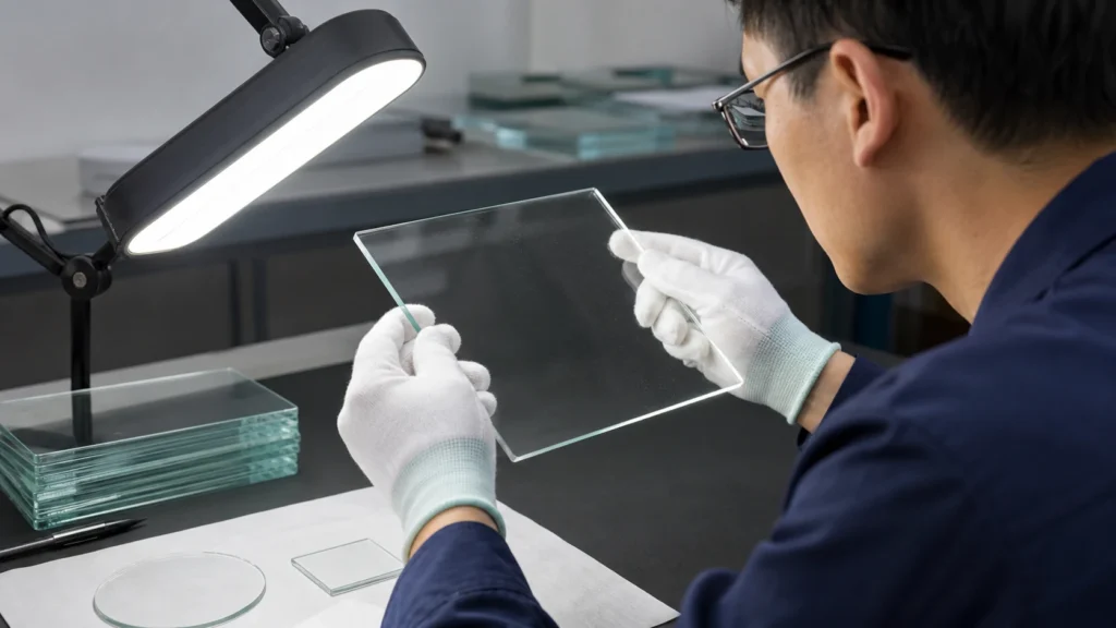
Achieving a given surface quality requires aligning the optical glass polishing process, inspection method, and cleaning protocol. The supplier will evaluate whether the requested scratch‑dig is compatible with the glass type and thickness. Extremely tight specifications on thin or large parts introduce handling risks; engineering review determines the feasible limit. Inspection typically follows the standard’s comparison method (using a calibrated light source and reference plates) or, for high‑precision parts, microscopic or interferometric measurement. Final cleaning must remove all residue without introducing new scratches, and packaging—often individual trays or cleanroom‑bagged—prevents transit damage.
Coating Compatibility and Surface Preparation
If the component will receive an AR coating, ITO layer, or other functional film, the surface quality specification must consider coating adhesion. Coatings magnify substrate defects; a sub‑optimal scratch‑dig or high Ra can lead to pinholes or delamination. Specify the surface quality required before coating, and confirm that the cleaning and activation steps prior to deposition are part of the engineering review. Differing surface qualities on opposite faces (e.g., one polished, one ground) must be clearly noted.
RFQ Checklist: Surface Quality Essentials
- Identify the applicable standard (MIL‑PRF‑13830B, ISO 10110‑7, or company‑specific).
- State the scratch‑dig numbers for each critical surface; note where unequal specs apply.
- Provide surface roughness Ra or Rz value and measurement length.
- Indicate any special cleaning, handling, or packaging requirements.
- Include drawings that highlight evaluation areas and edge exclusions.
Send your drawings, material preferences, tolerance stack‑ups, and surface quality targets to initiate an engineering review. Our team will confirm manufacturability, suggest refinements, and provide an actionable quotation.
| Aspect | Typical Specifications | Key Considerations |
|---|---|---|
| Material | Fused silica, borosilicate, Borofloat 33, optical glass, sapphire | Hardness and chemical durability affect achievable polish quality. |
| Geometry | Windows, wafers, microfluidic chips, perforated plates | Aspect ratio and thickness influence flatness and handling risk. |
| Dimensional Tolerances | ±0.05 mm typical; tighter under review | Machining method and glass type dictate capability. |
| Flatness / TTV / Bow | λ/4 to λ/10; TTV < 5 µm for wafers | Polishing and lapping sequences are tailored to part size. |
| Surface Roughness (Ra) | ≤ 2 nm for optical, ≤ 0.8 µm for mechanical seals | Measured per ISO 4287; specifies micro‑texture, not defects. |
| Scratch‑Dig | 60‑40, 40‑20, 20‑10 per MIL‑PRF‑13830B | Defines discrete scratch and dig limits; inspection method defined by standard. |
| Coatings | AR, ITO, FTO, beam splitter | Surface quality directly affects coating adhesion and performance. |
| Edge Finish | Ground, polished, chamfered | Specify edge quality to avoid chipping and define handling safety. |
Frequently Asked Questions
What is the scratch-dig specification for optical glass?
The scratch-dig specification, defined by MIL-PRF-13830B or ISO 10110‑7, quantifies the allowable size and number of surface imperfections. It uses two numbers: the first indicates the maximum scratch width in microns, and the second the maximum dig diameter in hundredths of a millimeter. For example, 60‑40 permits scratches up to 60 µm wide and digs up to 0.4 mm diameter.
How do I choose between MIL-PRF-13830B and ISO 10110‑7 for surface quality?
MIL-PRF-13830B is commonly used in North America and defense applications, while ISO 10110‑7 is the international standard. The choice often depends on customer preference or regional practice. Both define scratch-dig classes, but ISO 10110‑7 uses a severity number rather than direct scratch width. Confirm which standard your supplier supports and reference it explicitly on drawings.
What does surface roughness Ra mean for glass components?
Ra (arithmetic average roughness) quantifies the micro-texture of a surface by measuring the average deviation from the mean line over a sampling length. For precision glass, typical Ra values range from ≤ 2 nm for high-quality optical surfaces to 1-3 µm for ground surfaces. Ra is specified separately from scratch-dig, as it describes texture rather than isolated defects.
How does surface quality affect coating adhesion?
Surface quality directly impacts coating adhesion and durability. Scratches, digs, and excessive roughness can create nucleation sites for defects, leading to poor adhesion, pinholes, or delamination. A smooth, defect-free surface with an appropriate micro-roughness provides the best substrate for optical coatings. Specify surface quality before coating and include cleaning steps in the process review.
Can I specify different surface qualities for different areas of a glass part?
Yes, many precision glass components require distinct surface qualities on different faces or zones. For example, an optical window may have a tight scratch-dig on the clear aperture while edges are left ground. Clearly mark these zones on the drawing and note any transition areas. This helps the supplier optimize polishing and inspection efforts.