
Key Takeaways
- Precision glass drilling uses diamond tools, ultrasonic machining, or laser filamentation to achieve hole diameters from 0.2 mm up, with positional accuracy of ±10 μm.
- Fused silica, borosilicate, and alkali-free glass are common inputs, selected based on thermal, optical, and chemical requirements of the end application.
- In-line metrology checks include thickness, flatness, hole diameter, edge chipping, and surface quality to ensure consistent output across large volumes.
- Drilling is performed before any chemical or thermal strengthening to avoid stress-induced fractures around holes.
- Scalable production from prototypes to over 100,000 units per month is enabled by CNC automation and statistical process control.
The Core of Precision Glass Drilling: How We Make Custom Holes and Through Features
Precision glass drilling for custom holes and through features is not a single-step operation—it is a controlled sequence of advanced machining stages built on material science, CNC engineering, and metrology. For B2B buyers sourcing glass wafers, microfluidic chips, or optical windows with exact hole patterns, the difference between a functional component and scrap lies in the process control from blank selection to final cleaning. The most critical point: drilling precision is defined not only by hole diameter and position tolerance, but by edge chipping, wall taper, and micro-crack propagation—factors that directly impact downstream yield in semiconductor, biomedical, and optical assemblies.
Base Materials and Inputs
Choosing the right glass substrate is the first quality decision. Common precision glass types include:
- Fused silica (JGS1, JGS2): High-purity, low thermal expansion, excellent UV-to-IR transmission. Preferred for laser optics and semiconductor wafer carriers.
- Borosilicate (BF33, Borofloat 33): Good thermal shock resistance and chemical durability. Used in microfluidics and lab-on-chip devices.
- Soda-lime glass: Economical for cover glasses and display applications where optical clarity and flatness are sufficient.
- Alkali-free glass (e.g., AF32 eco): Designed for TFT-LCD and electronic applications to prevent ion migration.
- Optical glass (BK7, etc.): High refractive index homogeneity for lenses and prisms.
- Sapphire: Extreme hardness and scratch resistance, used for watch windows and armor.
All incoming material is verified for coefficient of thermal expansion, refractive index, and internal stress using polarimetry to prevent warpage during drilling.
Step-by-Step Manufacturing Stages
Cutting and Scribing
Large-format sheets are cut into blanks using CNC scribe-and-break machines or diamond wire saws. This stage sets the outer dimensions with a positional tolerance of ±0.1 mm while minimizing edge defects that could propagate during hole drilling.
Grinding and Lapping
Blanks are ground to achieve controlled thickness and parallelism. Double-side lapping with aluminum oxide or diamond slurries yields a surface flatness of λ/4 per 25 mm and thickness tolerance down to ±0.01 mm. This uniformity is essential because variations affect laser focal point or mechanical drill pressure.
Precision Drilling
Holes are created using one or a combination of methods:
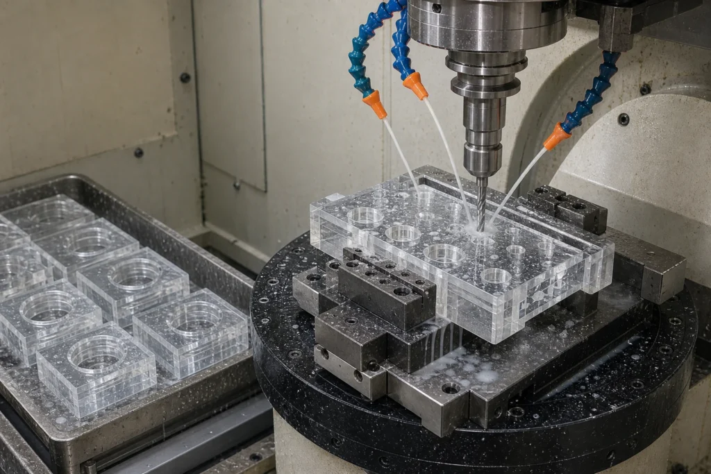
- CNC diamond drilling: For holes Ø0.8 mm and above in thickness up to 10 mm. A diamond-impregnated tool rotates at high speed with water-based coolant, producing straight walls and minimal chipping.
- Ultrasonic machining: For brittle materials like borosilicate, ultrasonic frequency vibration of a carbide tool in abrasive slurry creates holes down to Ø0.2 mm with tapered walls and no thermal stress.
- Laser filamentation (TGV): For glass wafers with micro vias, femtosecond laser pulses create a filament without melting, enabling high-aspect-ratio holes (10:1) with <5 μm taper and no micro-cracks.
- Laser ablation (UV/CO₂): Used for patterning or larger through-features, often followed by acid etching to remove recast layer.
All drilling is performed before tempering to avoid stress concentration. Hole position accuracy is maintained by CCD optical alignment systems, achieving ±10 μm registration to fiducials.
Edging and CNC Machining
After drilling, the outer contour may be CNC-ground to final shape with chamfers or notches. This step also removes any micro-cracks at edges from previous operations.
Polishing
Double-side polishing with ceria or colloidal silica achieves surface roughness Ra <1 nm for optical surfaces and scratch-dig 10-5 per MIL-PRF-13830. Holes are protected during polishing to prevent edge rounding.
Cleaning
Multi-stage ultrasonic cleaning with alkaline and DI water rinses, followed by Class 100 cleanroom drying, ensures no particulate contamination remains inside holes or on surfaces.
Coating
Optional functional coatings—AR, ITO, FTO, reflective, or protective—are applied using magnetron sputtering or evaporation. Masking may be used to keep holes clear.
Strengthening
Chemically strengthened (ion-exchange) in a potassium salt bath for soda-lime glass, or thermal tempering for thicker borosilicate, enhances resistance to breakage. Holes act as stress risers; the strengthening profile is adjusted to maintain >200 MPa surface compression near edges.
Equipment and Techniques That Define Quality
Advanced CNC drilling machines combine air-bearing spindles, linear motor stages, and in-process vision to achieve micron-level repeatability. For high-volume glass wafer with holes, double-side polishing platforms and automated laser systems ensure batch consistency. Coatings are deposited in vacuum chambers with an in-situ thickness monitoring, guaranteeing ±3% uniformity across an entire cassette.
Cleanroom conditions (ISO Class 7 or better) prevent particle-induced defects during drilling and assembly. Laser filamentation is emerging as the go-to for glass interposers and microfluidic TGV applications.
In-line Quality Checkpoints During Production
Every process stage includes metrology:
- Thickness, total thickness variation (TTV), and bow/warp measured by laser interferometry.
- Hole diameter and roundness checked with vision measurement systems or air gauges.
- Edge chipping evaluated at 50x magnification per ISO 21254.
- Surface quality inspected using scratch-dig comparators.
- Transmission and reflection verified with spectrophotometers for coated parts.
- Dimensional conformance to GD&T callouts (true position, profile) is maintained within ±5 μm.
Capacity, Consistency and Scalability for Bulk Orders
Through parallel workstations and CNC automation, production scales from prototypes in single digits to high-volume orders exceeding 100,000 units monthly. Process controls and SPC data tracking ensure that the first article and the millionth share identical specifications. Tool wear is monitored and compensated automatically. Standard lead times for custom orders start from 2–3 weeks after drawing approval; expedited runs are available.
Request a Process Overview Tailored to Your Application
Send your CAD file or sketch, tolerance requirements, and target volume. We will return a detailed manufacturing flow, feasibility analysis, and quotation—with complete transparency on process capabilities and inspection protocols.
Key Facts About Precision Glass Drilling
| Aspect | Details |
|---|---|
| Hole diameter range | 0.2 mm to >15 mm, depending on method |
| Minimum thickness | 0.1 mm for laser; 0.5 mm for mechanical |
| Position accuracy | ±10 μm with optical alignment |
| Typical surface quality | 10-5 scratch-dig, Ra <1 nm |
| Edge chipping | <0.2 mm on hole rims |
| Strengthening methods | Chemical tempering (ion-exchange) or thermal tempering |
| Batch scalability | Prototype to >100k units/month |
Frequently Asked Questions
What are the best methods for drilling micro-holes in borosilicate glass for microfluidics?
For microfluidic chips requiring holes below 1 mm, ultrasonic machining and femtosecond laser filamentation are top choices. Ultrasonic drilling uses abrasive slurry and a vibrating tool to produce tapered, crack-free holes, while laser filamentation creates high-aspect-ratio vias with smooth walls and minimal thermal damage. Both methods are compatible with BF33 and Borofloat 33 substrates.
How does laser glass drilling compare to diamond drilling for high-volume production?
Laser drilling (especially filamentation) offers higher speed, non-contact processing, and excellent hole quality for thin glass wafers, while diamond drilling is often more cost-effective for larger holes and thicker materials. For quantities exceeding tens of thousands, laser systems provide better repeatability and can be integrated into automated lines, reducing labor. The choice depends on aspect ratio, edge chipping requirements, and material thickness.
Can you drill holes in strengthened glass without shattering?
Drilling holes in already tempered glass is not recommended because the internal stress balance will be disrupted, leading to immediate fracture. All holes and custom features must be drilled before the strengthening process. After drilling, the glass can be chemically or thermally tempered, provided the hole edges are well-sealed and the strengthening profile is controlled to maintain compressive stress near the rims.
What tolerance can you hold for hole position on a glass wafer?
With optical alignment systems and precision CNC stages, typical positional accuracy is ±10 μm relative to fiducial marks. For less demanding applications, ±50 μm is standard. The tolerance depends on the drilling method, fixturing, and the glass wafer’s dimensional stability. ISO 2768 fine or medium tolerances are common references.
Is it possible to drill complex through-features like slots or irregular shapes in glass?
Yes, precision glass drilling machines equipped with CNC interpolation can create slots, squares, and other 2D profiles. For intricate geometries, laser machining combined with wet etching or multiple drilling passes is used. The process requires careful path planning to avoid stress concentration and cracking at corners.