
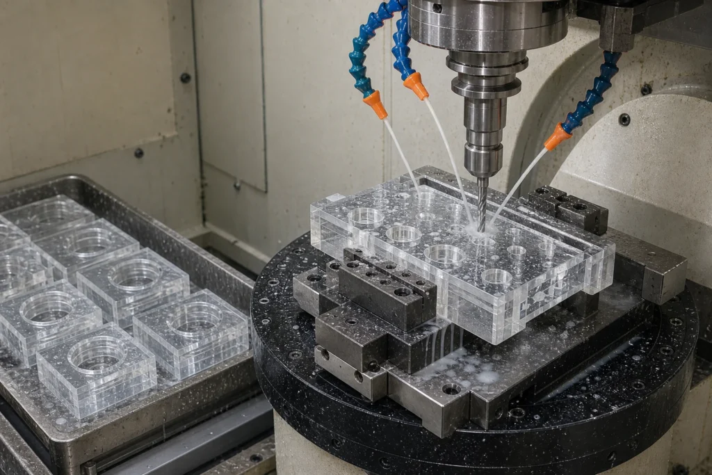
Quick answer: Drilling Optical Glass covers Optical Glass (CTE 7.1 x 10^-6 /K, 350 nm – 2.0 um); Drilling to +/-0.02 mm hole position. Prototypes ship in 5-10 working days.
The combination of Optical Glass and Drilling comes up constantly in RFQs for a reason – the material offers striae and stress-birefringence control, and Drilling is the right way to get accurate geometry into it. Expect +/-0.02 mm hole position and exit-chip controlled below 0.1 mm.
The numbers
| Material | Optical Glass (N-BK7, H-K9L and filter glass sets) |
|---|---|
| Thermal expansion (CTE) | 7.1 x 10^-6 /K |
| Service temperature | 400 C (Tg 557 C) |
| Transmission range | 350 nm – 2.0 um |
| Density | 2.51 g/cm3 |
| Knoop hardness | 610 kg/mm2 |
| Refractive index | 1.5168 @ 587 nm |
| Stock thickness | 0.30 – 50 mm |
| Maximum blank size | 300 mm diameter |
| Process | Drilling |
| Working tolerance | +/-0.02 mm hole position |
| Minimum feature | 0.15 mm laser / 0.5 mm mechanical |
| Surface finish | exit-chip controlled below 0.1 mm |
| Thickness window | 0.1 – 30 mm |
| Edge condition | optional chamfered hole entry |
| RFQ inputs | PDF/DXF/STEP drawing, quantity brackets, surface and edge spec |
Design guidance
Three items decide most of the cost and lead time on this work:
- Material note: index-certified blanks must be oriented and serialized through the shop to keep melt traceability.
- Process boundary: hole-to-edge distance should stay above 1.5x thickness to protect strength.
- Over-specification is the quiet budget killer: a 20/10 scratch-dig face costs roughly three times an 80/50 face, so grade each surface individually.
The full rules live in our tolerance design guide and holes and edges design guide.
What the process holds
Drilling earns its place through through-holes, blind holes and countersinks at densities beyond 1,000 holes per part. Its boundary condition – hole-to-edge distance should stay above 1.5x thickness to protect strength – is the first thing our DFM review checks.
Beyond this page, Optical Glass routinely runs through cnc machining, laser cutting, dicing, polishing in our shop – most real parts combine two or three of these steps.
Application context
drilling optical glass shows up across optical sensors (sensor windows, filter caps, lens covers); machine vision (camera windows, ring-light diffusers, calibration plates); ccd inspection equipment (CCD cover plates, reference grids, stage glass). Background reading on the underlying material science: RP Photonics: optical glass.
The fastest route to a quote is geometry: use the 3D builder below, draw a dimensioned 2D drawing from it, or open the site-wide custom glass machining 3D + 2D builder for fully custom parts.
Engineers scoping this work usually also review precision glass drilling, AR coated glass materials, glass-bottom microplates.
Frequently asked questions
What equipment runs the drilling work?
Diamond core drills, ultrasonic assist and laser percussion heads.
Is there a minimum order for drilling optical glass?
No. Single prototypes are accepted, and pricing steps down at 10, 100 and 1,000 pieces.
How fast can prototypes ship?
Machined prototypes ship in 5 – 10 working days. Coated or bonded parts add 1 – 2 weeks depending on queue slots.
What files do you need for a quote?
A dimensioned PDF plus DXF or STEP geometry. If only a sketch exists, our drawing review service formalizes it before quoting.
Do parts ship with inspection data?
Dimensional reports, surface certificates and material certs per melt are available; specify the level on the RFQ.
Specifications on this page were last reviewed by our engineering team in September 2026.