
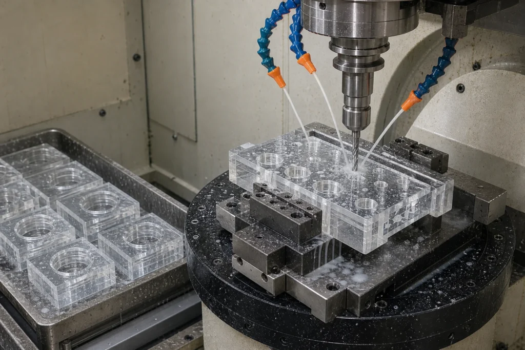
Quick answer: Drilling Borofloat 33 covers Borofloat 33 (CTE 3.25 x 10^-6 /K, 350 nm – 2.0 um); Drilling to +/-0.02 mm hole position. Prototypes ship in 5-10 working days.
Ask any process engineer what makes borofloat 33 difficult and the answer is specific: float tin side must be tracked when parts see coating or bonding steps. Our drilling line is tooled around exactly that – diamond core drills, ultrasonic assist and laser percussion heads – holding +/-0.02 mm hole position on parts from 0.1 – 30 mm thick.
Specification envelope
| Material | Borofloat 33 (SCHOTT float production, wafer grade) |
|---|---|
| Thermal expansion (CTE) | 3.25 x 10^-6 /K |
| Service temperature | 450 C continuous |
| Transmission range | 350 nm – 2.0 um |
| Density | 2.23 g/cm3 |
| Knoop hardness | 480 kg/mm2 |
| Refractive index | 1.471 @ 587 nm |
| Stock thickness | 0.70 – 25.4 mm |
| Maximum blank size | 500 x 500 mm |
| Process | Drilling |
| Working tolerance | +/-0.02 mm hole position |
| Minimum feature | 0.15 mm laser / 0.5 mm mechanical |
| Surface finish | exit-chip controlled below 0.1 mm |
| Thickness window | 0.1 – 30 mm |
| Edge condition | optional chamfered hole entry |
| RFQ inputs | PDF/DXF/STEP drawing, quantity brackets, surface and edge spec |
Process window
Drilling earns its place through through-holes, blind holes and countersinks at densities beyond 1,000 holes per part. Its boundary condition – hole-to-edge distance should stay above 1.5x thickness to protect strength – is the first thing our DFM review checks.
Beyond this page, Borofloat 33 routinely runs through dicing, polishing, coring, edge grinding in our shop – most real parts combine two or three of these steps.
DFM notes from the shop floor
Three items decide most of the cost and lead time on this work:
- Material note: float tin side must be tracked when parts see coating or bonding steps.
- Process boundary: hole-to-edge distance should stay above 1.5x thickness to protect strength.
- Over-specification is the quiet budget killer: a 20/10 scratch-dig face costs roughly three times an 80/50 face, so grade each surface individually.
The full rules live in our tolerance design guide and holes and edges design guide.
Who orders this
The recurring buyers of drilling borofloat 33: optical sensors (sensor windows, filter caps, lens covers); led packaging (groove covers, phosphor carriers, package windows); mems devices (cap wafers, TGV substrates, motion-sensor lids). Background reading on the underlying material science: SCHOTT BOROFLOAT product page.
Dimensions still moving? Configure this part live in the 3D builder below, or open the full custom glass machining 3D builder to start from a blank canvas.
For adjacent specifications, see precision glass drilling, Borofloat 33 selection guide, surface quality guide.
Frequently asked questions
What tolerances are achievable on Borofloat 33 parts?
Ground features hold +/-0.01 mm and lapped thickness reaches +/-0.003 mm. Float tin side must be tracked when parts see coating or bonding steps.
What thickness range do you stock for Borofloat 33?
Standard stock spans 0.70 – 25.4 mm, with blanks up to 500 x 500 mm. Other formats are sourced per order.
How does Borofloat 33 behave under heat?
CTE is 3.25 x 10^-6 /K and continuous service reaches 450 C continuous, which is what drives its use where float-glass flatness off the line matters.
What accuracy does drilling hold?
+/-0.02 mm hole position with minimum features of 0.15 mm laser / 0.5 mm mechanical. Hole-to-edge distance should stay above 1.5x thickness to protect strength.
Specifications on this page were last reviewed by our engineering team in July 2026.